Before installing the accessories – DR Power Power Take-Off (PTO) System User Manual
Page 11
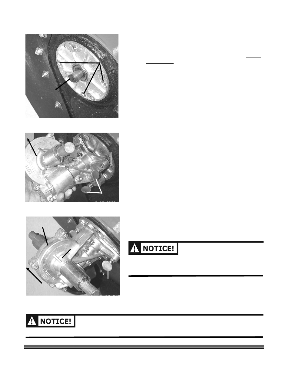
2. Hold the bearing shaft to prevent it from turning
using a screwdriver or the head-locking tool (Figure 2).
Install and tighten the shaft extension (
Figure
3) with
adjustable wrench or 5/8" wrench until snug. Do not
over tighten.
Shaft Extension
Inserts
Figure 3
Insert
3. Rotate the transmission to align its shaft with the
slotted hole in the shaft extension (Figure 4), sliding
the transmission up against the lower bearing plate
and rotating it to align the three captive fasteners with
their respective inserts (Figure 4).
Front of
machine
CALL TOLL FREE 1-800-DR-OWNER
7
4. Install the transmission with the transmission’s L
marking on the trimmer’s left side (
Figure 5
).
5. First, tighten each of the three captive thumbscrews
finger tight. Then use a wrench or pliers to tighten
each screw alternately.
Captive Screws
Figure 4
Figure 5
Front of
machine
L marking
Bulge
Captive
Screw
THE BULGE ON THE TRANSMISSION MUST FACE TOWARD
CHINE FOR PROPER
THE FRONT OF THE MA
PERFORMANCE (
FIGURE 5
).
DO NOT OVER TIGHTEN THE THUMBSCREWS OR DAMAGE MAY OCCUR.