DR Power Power Take-Off (PTO) System User Manual
Page 15
2. Replace the removed bolt with the supplied black
plastic button (
Figure
11). Simply push the button
into the hole or gently tap in place with a hammer.
Figure 11
Insert plastic button
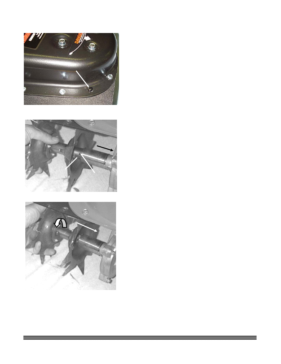
3. Install the aerator or cultivator on the trimmer’s
right by sliding the attachment’s axle over the shaft
of the transmission, rotating the attachment to
align the slot in the axle with the drive pin and
pushing the attachment axle toward the
transmission (
Figure 12
).
Note: The right side attachments have a red cap and 2
semi-circular notches in the axle (see
Figure 6
on page 10).
There is a spring that you will compress as you push the
attachment onto the shaft until the drive pins bottom on
the slot in the attachment’s axle. This will require a fair
amount of force to overcome the spring tension.
4. When the attachment axle is inserted completely,
rotate the attachment clockwise until it reaches the
end of the J-slot (
Figure 13
).
Push in
Drive Pin
CALL TOLL FREE 1-800-DR-OWNER
11
Note:
When the attachment is released, it should lock into
the end of the J-slot and should not turn in either direction.
Check to see that the attachment is locked into place by
trying to turn it both clockwise and counterclockwise.
J-Slot
5. To install the aerator or cultivator left axle, repeat
the instructions above.
Figure 12
Compress
Spring
Turn and release
to lock in J-Slot
Figure 13
Note: The attachment’s left axle has a black cap and does
not have a semi-circular notch at the end of the axle near the
J-slot (see Figure 6 on page 10).