Installing the gas spring/s – DR Power Tow-Behind 9.59 Premier (September 2014 - Present) User Manual
Page 11
CONTACT US AT www.DRpower.com 11
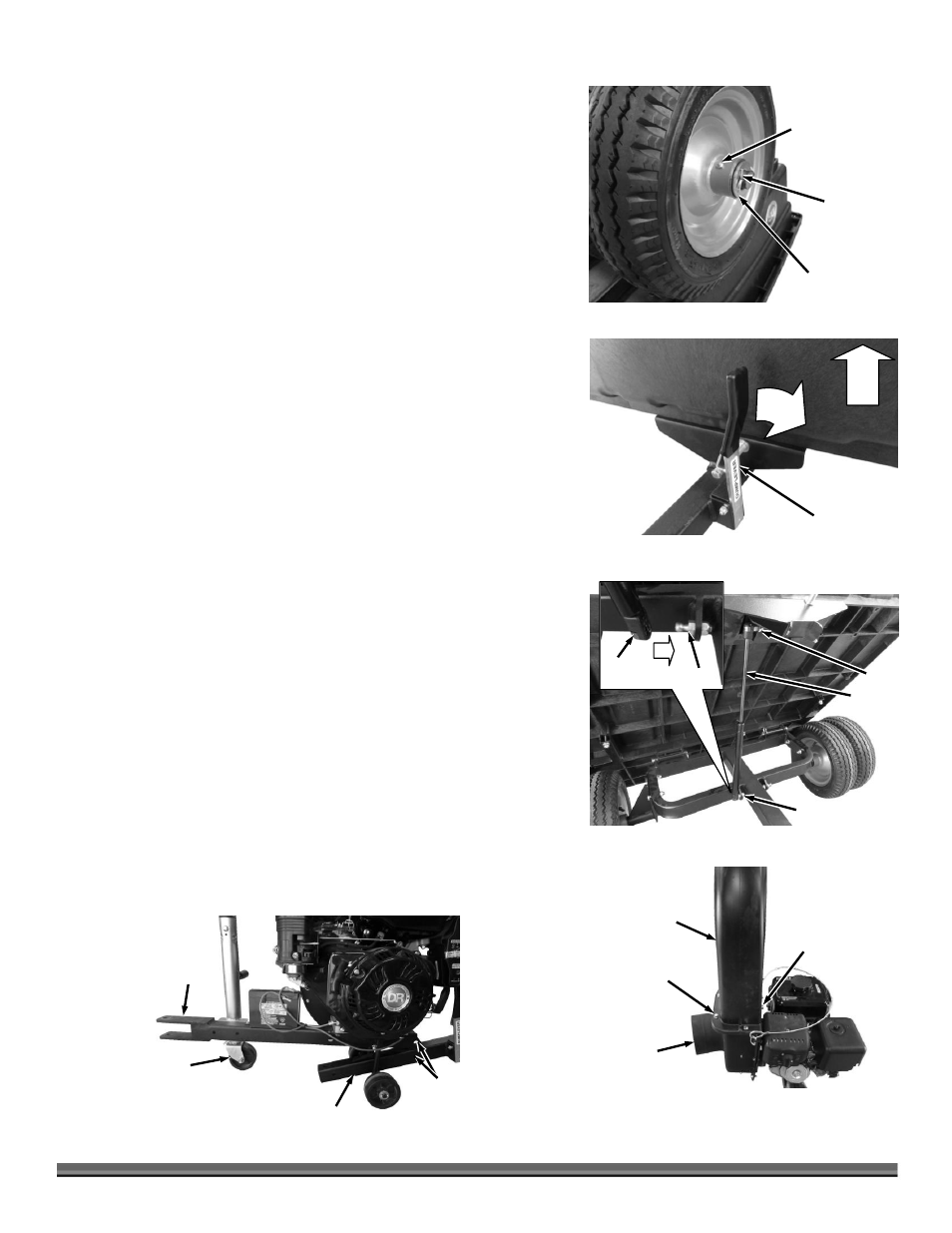
5. Install a Wheel (second wheel for Dual Wheel models) with the Valve Stem
facing out and place a Washer against the Wheel (Figure 11).
6. Secure the Wheel/s onto the Axle with a Cotter Pin. Use Pliers to bend the
ends of the Cotter Pin to secure the Wheels.
7. Repeat for the Wheel/s on the opposite side.
8. Tip the Cart over onto the Wheels.
Installing the Gas Spring/s
Note: The Premier uses one Gas Spring. The Pro and ProXL use two Gas Springs.
1. Tilt the Cart Bed up by pulling the Lift Handle out and lifting up on the front
of the Cart (Figure 12).
Note: In the next step, the Gas Spring needs to be installed with the larger end
attached to the Frame and the thin Shaft end to the Cart Bed.
2. Insert the right side Gas Spring onto the Studs by pressing the holes in the
ends of the Gas Spring over the Studs. They will snap into place. (Figure 13).
3. For Pro and ProXL: Do not install the second Gas Spring at this time.
4. Leave the Cart in the up position for the following procedure.
Installing the Power Unit (Use Power Unit Hardware Package, see
Figure 6)
Tools Needed:
Two 9/16" Wrenches
Two 3/4" Wrenches
Flat Head Screwdriver or 5/16" Wrench
1. Place the Outlet Chute on top of the Impeller Housing and loosely install the
Engine side with a 5/16-18 X .75" Bolt, Lock Washer and Flat Washer using a
9/16" Wrench (Figure 14).
2. Secure the flange of the Outlet Chute and Impeller Housing with four 5/16-
18 X .75" Bolts and 5/16-18 Locknuts using two 9/16" Wrenches. For proper
alignment, tighten the two flange Bolts nearer the engine first, then tighten
the rest of the hardware.
3. Machines with Jacks: Remove the Locking Pin from the lower portion of the
Jack and crank the Jack Handle so the Power Unit Tow Hitch is lowered as far
as it will go towards the ground (Figure 15).
4. Move the Engine unit into position at the front of the Cart with the Tow Hitch
facing
forward and
the rear
holes
aligned.
Dump Lever
Figure 12
1
2
2nd Dual Wheel
or single Wheel
(Valve Stem and
Grease Fitting
facing out)
Figure 11
Washer
Cotter Pin
Jack
(Standard Equipment
on Pro and ProXL)
Figure 15
Cart Frame
Rear
Holes
Tow
Hitch
Outlet Chute
Figure 14
Impeller
Housing
Bolts and
Locknuts
Bolt, Lock Washer
and Flat Washer
Gas
Spring
Figure 13
Stud
Stud
Stud
Gas
Spring