Installing the log table kit, Installing log table with support leg – DR Power RapidFire 3.0 HP DR (June 2014 - Present) Operating Manual User Manual
Page 10
10
DR
®
PREMIER RAPIDFIRE™ LOG SPLITTER
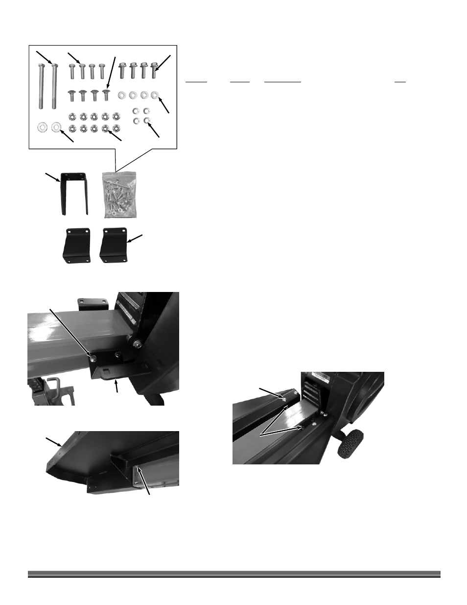
Installing the Log Table Kit
Parts Supplied (
Figure 6):
Item # Part
# Description
Qty
1 .................... 34503 ....... Bracket, Log Table ....................................... 1
2 .................... 32105 ....... Mount, Tray ................................................. 2
3 .................... 33351 ....... Bolt, Hex, Flange, 3/8-16 X 1.25" ................ 4
4 .................... 22912 ....... Bolt, HHCS, 3/8-16 X 4.5", GR5, ZP ........... 2
5 .................... 32104 ....... Bolt, Carriage, 3/8-16 X 1", GR5, ZP ........... 4
6 .................... 15043 ....... Bolt, HHCS, 3/8-16 X 1-1/4", ZP ................ 4
7 .................... 33333 ....... Nut, Nylon Lock, Flanged, 3/8-16............... 10
8 .................... 18081 ....... Washer, Lock, 3/8" ...................................... 4
9 .................... 11239 ....... Washer, Flat, 3/8", USS .............................. 2
10 .................. 11241 ....... Washer, Flat, 5/16" USS, ZP ....................... 4
Not Shown .... 31363 ....... Table, Log .................................................... 1
Installing Log Table with Support Leg
1. Place a Jack Stand under the Beam to lift it up.
2. Loosely install a Tray Mount on both side of the Beam with Flange Bolts and
Locknuts using two 9/16" Wrenches (Figure 7).
3. Install the front of the Tray to the Beam with four Bolts, Flat Washers and
Lock Washers using a 9/16" Wrench (Figure 8).
4. Install the Table to the Tray Mounts with four Carriage Bolts and Locknuts
using a 9/16" Wrench (Figure 9).
9
Figure 6
7
8
10
3
6
4
5
1
2
Tray Mount
Figure 7
Bolts and
Locknuts
Tray
Figure 8
Bolt, Lock Washer
and Flat Washer
Beam
Carriage Bolt
and Locknut
Figure 9
Table
Mounts