DR Power Lawn Aerator User Manual
Page 15
CONTACT US AT www.DRpower.com 15
2.
Remove the two Bolts and Flat Washers that secure the Belt Cover using a
7/16" Wrench and remove the Cover.
3.
Block up the front of the machine so you have better access to Engine
hardware.
4.
Remove the four Bolts, five Flat Washers and four Locknuts that secure the
Engine to the Frame using two 1/2" Wrenches (Figure 20). For Electric Start
models the Ground Bolt has two Nuts and two Lock Washers instead of a
Locknut.
Note: Keep track of the locations of the Flat Washers, Star Washers and Locknuts to
ensure you assemble them in the correct locations. Pay special attention to
the Ground Wire Location between two Lock Washers at the front left
mounting position. See illustration in Chapter 6 for reference of location
and order if needed.
5.
If you have a manual start machine the Engine can be removed from the
Frame. For Electric start machines rotate the Engine with the Wire Harness
attached enough so the Belt can be removed from the Pulley (Figure 21).
Note: The Belt can be loosened from the groove of the Crank assembly to allow
more slack to remove the Belt from the Engine Pulley.
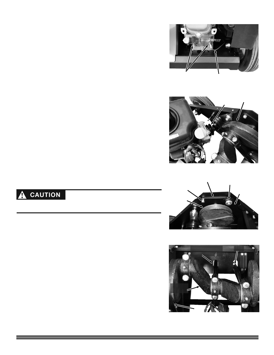
6.
Use a 1" or Adjustable Wrench (inside of Frame) and a 1/2" Wrench
(outside of Frame) to remove the two Pivot Nuts and Bolts from the Tine
Position Arms to release the Arms (Figure 22).
7.
Use two 1/2" Wrenches to remove the three Locknuts (each side) that
secure the Bearing Plates to the Frame while leaving the Bolts in place.
8.
Carefully remove the Bolts from the Bearing Plates and Frame as you let the
Bearing Plates rest on the shoulders on the inside of the Frame.
9.
Use the top lip of the Bearing Plate to pull the Tine Assembly from the
machine.
10.
Remove the old Belt and position a new Belt onto the Tine Assembly Belt
groove.
11.
Lift the Tine Assembly with the new Belt into the Aerator Frame and rest it
on the Frame Shoulders. Ensure that you insert the Tines into the slots of
the Tine Position Plate (Figure 23).
12.
Continue the assembly by working in the reverse order starting at step 8 and
working back to step 1.
13.
Adjust the Drive Cable length for proper Belt tension. See “Adjusting the
Drive Cable” on the next page.
Pivot Nut
Figure 22
Three Bearing
Plate Lock Nuts
Crankshaft
Tine Position
Arm
Bearing Plate
Engine
Hardware
Figure 20
Ground Wire
Belt
Figure 21
Engine
Pulley
Rotate
Engine
The Tine Assembly is heavy and awkward to lift out of the machine. Have
another person help with the removal of the Tine Assembly to avoid injury.
Belt
Figure 23
Tines
Three Slots in Tine
Position Plate
Tine crank
Assembly