Fieldpiece SC44 - Mini Clamp Meter User Manual
Using the best range, Backlight (sc46), Symbols used
Using the best range
Autoranging meters automatically select the range
that gives you the best resolution. For example, when
measuring 24VAC, the meter will select the 40VAC
range and display "24.0". In the 400Vrange, you'd
see "24" and in the 4V range you'd see "OL" for over-
load. When an n (nano), m (micro), m (milli), K, or M
shows up in the display, you must multiply by 10
-9
,
10
-6
, 10
-3
, 10
3
, and 10
6
respectively.
You can manually select the range by pressing the
O button until you get the range you want. This can
keep the decimal from bouncing around when meas-
uring a parameter that varies from just a little below
the top of the range to a little over.
Backlight (SC46)
The SC46 has a backlight that allows the user to
read the display in any lighting conditions. Make sure
the area being tested is well lit. The backlight comes
on when the button is depressed and stays on for
60sec before turning off to conserve battery life.
Symbols used:
Caution, risk of electric shock
Caution, refer to manual.
Ground
Double insulation
OPERATOR’S MANUAL
CAT.III
CLAMP
400A
300V
NCV
For your safety...
General: Disconnect the test leads before opening
the case. Inspect the test leads for damage to the
insulation or exposed metal. Replace if suspect.
Never ground yourself when taking electrical meas-
urements. Do not touch exposed metal pipes, outlets,
fixtures, etc., which might be at ground potential.
Keep your body isolated from ground by using dry
clothing, rubber shoes, rubber mats, or any approved
insulating material. When disconnecting from a cir-
cuit, disconnect the "RED" lead first, then the com-
mon lead. Work with others. Use one hand for test-
ing. Turn off power to the circuit under test before cut-
ting, unsoldering, or breaking the circuit. Keep your
fingers behind the finger guards on the probes. Do
not measure resistance when circuit is powered. Do
not apply more than rated voltage between input and
ground.
All voltage tests: All voltage ranges will withstand
up to 600V. Do not apply more than 600VDC or
600VAC rms.
AC tests: Disconnect the meter from the circuit
before turning any inductor off, including motors,
transformers, and solenoids. High voltage transients
can damage the meter beyond repair. Do not use
during electrical storms.
Maintenance
Clean the exterior with clean dry cloth. Do not use
liquid.
Battery replacement: When the multimeter dis-
plays " " the battery must be replaced.
Disconnect and unplug leads, turn meter off, and
remove the battery cover. Replace both of the two
AAA (1.5V) batteries.
Limited warranty
This meter is warranted against defects in materi-
al or workmanship for one years from date of pur-
chase. Fieldpiece will replace or repair the defective
unit, at its option, subject to verification of the defect.
This warranty does not apply to defects resulting
from abuse, neglect, accident, unauthorized repair,
alteration, or unreasonable use of the instrument.
Any implied warranties arising from the sale of a
Fieldpiece product, including but not limited to
implied warranties of merchantability and fitness for a
particular purpose, are limited to the above.
Fieldpiece shall not be liable for loss of use of the
instrument or other incidental or consequential dam-
ages, expenses, or economic loss, or for any claim of
such damage, expenses, or economic loss.
State laws vary. The above limitations or exclu-
sions may not apply to you.
Obtaining service
Call Fieldpiece Instruments for one-price-fix-all
warranty service pricing. Send check or money order
for the amount quoted. Send the meter freight pre-
paid to Fieldpiece Instruments. Send proof of date
and location of purchase for in-warranty service. The
meter will be repaired or replaced, at the option of
Fieldpiece, and returned via least cost transportation.
www.fieldpiece.com
!
AUTO-RANGING DIGITAL
CLAMP METERS:
SC44, SC45, SC46
Description
The mini clamp-on meters are made for the tech-
nician who is looking for a small, low cost meter that
has most of the functions he needs, day in and day
out, without some of functions and convenience fea-
tures available on bigger meters.
Non-contact voltage
With the grey tip on the amp clamp head close to
an AC voltage, press and hold the NCV button. The
NCV LED will light and the beeper will beep. The
closer you get to AC voltage, the louder the beep.
The NCV function is sensitive enough to detect
24VAC on thermostats. (24V to 600V, 50Hz to 60Hz)
Capacitance (SC45 amd SC46)
For motor-start and motor-run capacitors.
Disconnect the capacitor from power first. If the
capacitor is connected to the meter and “dsc” symbol
is shown on the LCD, it means there is voltage exist-
ing in the tested capacitor and needs to be dis-
charged before testing. Short the terminals to dis-
charge the capacitors. Disconnect any resistors that
might be between the terminals of the capacitor.
Hold
Press HOLD once to keep the latest reading dis-
played on the meter in the memory. Press the HOLD
button again to go back to normal mode.
True RMS (SC46)
Digital multimeters use two different types of AC
sensing. The most common is average sensing, nor-
malized to a true RMS value of a sine wave. The
other is true RMS sensing. The actual true RMS
value is sensed. Either sensing method will give the
same results on a clean sine wave but they may dif-
fer on a non-sinusoidal waveform.
Temperature (SC45 and SC46)
Plug any K-type thermocouple directly into the
meter to measure temperature. Temperature meas-
urement will be accurate even in fast changing envi-
ronments because of excellent temperature compen-
sation. No thermocouple adapter is required.
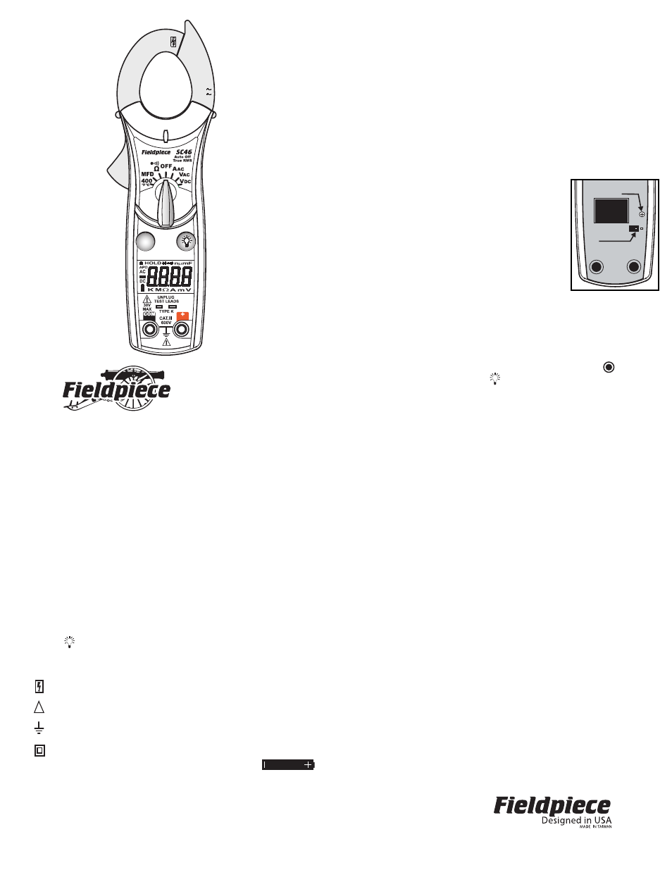
Field Temperature calibration
(SC45 & SC46)
For accuracies of
±1°, calibrate to a known tem-
perature. A glass of stabilized ice water is very close
to 32
°F (0°C) and is usually very convenient but any
known temperature can be used.
1. Select 400
°F/C range and connect thermocouple.
2. Remove back case (2 screws on back, one near
clamp, other near base). Leave battery cover
attached so batteries stay
within back case.
3. Stabilize a large cup of ice
water.
4. Immerse the thermocouple
tip and let it stabilize.
5. To change the temperature
scale to
°C, close the
jumper just below VR5.
6. Adjust VR5 calibration pot
with a small screwdriver to
get within 0.1
° of 32°F
(0°C). Each 1/4 turn should adjust the tempera-
ture about 3°, no more than 10° total. There’s no
need rotating the screw more than 360°; doing so
gets you back to where you started.
7. Attach case without screws to preview the tem-
perature and continue until you have it dialed in.
Disable auto off
Set to OFF position, press and hold (SC44 and
SC45) or (SC46) button while turning rotary dial to
desired range position. Release the button when
LCD displays normally. Note: “APO” annunciator will
be missing from the display. The Auto Power Off
mode is on when “APO” indicated on the display.
VR5
Jumper
v14