Fieldpiece SDP2 - Dual In-Duct Psychrometer User Manual
Fieldpiece, Dual in-duct psychrometer, Quick start
01
03
06
02
05
04
07
09
12
08
11
10
Quick Start
1. Power on your SDP2 by holding the
button for 1 second.
2. Select mode with the TEET/ΔT
button: Target Evaporator Exit
Temperature, Target Temp Split, or
Normal (real-time return and supply.)
3. Press the PARAM button to cycle
between dry bulb, relative humidity,
wet bulb, dew point, and enthalpy.
4. Insert sensing probes into duct or
plenum for in-duct measurements.
5. Hold SYNC to pair and send all
measurements to Fieldpiece model
HG3 or SMAN4 Analyzers.
Certifications
C-Tick (N22675)
CE
WEEE
FCC
RoHS Compliant
Description
The two probes each simultane-
ously measure temperature and
RH%. One goes before the evapo-
rator (RETURN) and one goes after
the evaporator (SUPPLY). These four
measurements can be displayed or
used in calculations to display the
actual temperature split (delta T), the
target temperature split, the actual
exit evaporator temperature, or the
target exit evaporator temperature
(TEET), plus the difference between
the actual and target. Enthalpy (BTU/
LBM) and Dew Point can also be dis-
played.
The TEET takes into consideration
the latent heat used to condense
water from the air, while a simple 20°
temperature split ignores latent heat.
TEET, developed by Fieldpiece, is an
intuitive test allowing you to aim for
a target value rather than a target
difference between two values.
The 38"(96cm) telescoping probe
with laser etched ruling and flattened
edges allows you to locate proper
measurement points within a duct
and ensures that your probe is prop-
erly aligned. The dual display, bright
backlight, and rugged rubber boot
with probe clips make sure the SDP2
is ready for any job.
Maintenance
Clean the exterior with a dry cloth.
Do not use liquid.
Battery Replacement
Turn your SDP2 off, remove rub-
ber boot, unscrew battery cover, and
replace 9V battery.
Fieldpiece
Dual In-Duct
Psychrometer
OPERATOR'S
MANUAL
Model SDP2
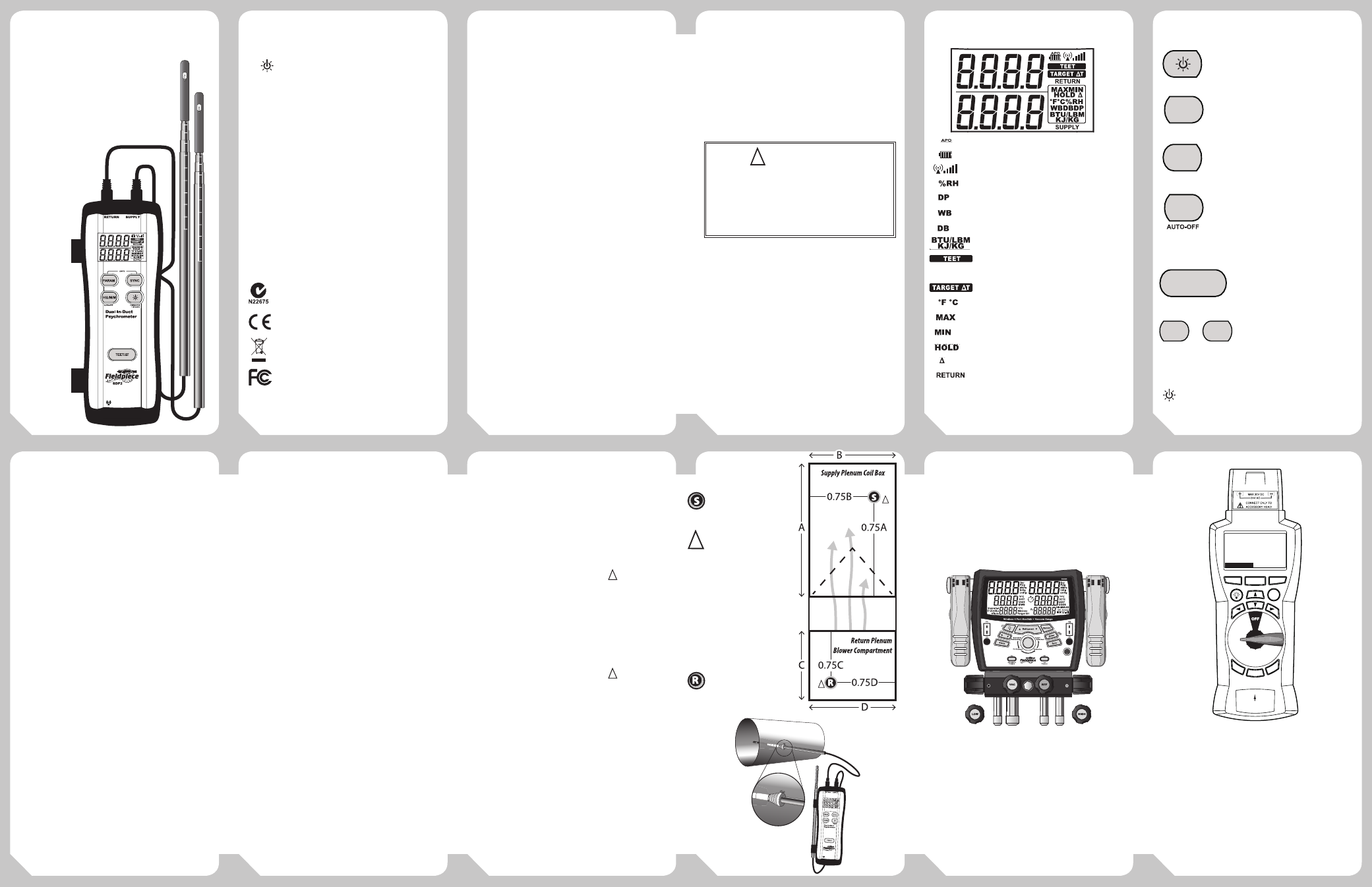
Display
Auto Power Off Enabled
Battery Life
Wireless Signal Strength
Relative Humidity
Dew Point
Wet Bulb
Dry Bulb
Enthalpy
Target Evaporator Exit
Temperature
Target Dry Bulb Temp Split
Temperature
Maximum Display
Minimum Display
Hold Display
Δ Display (Return-Supply)
Top Display Shows Return
Bottom Display Shows Supply
or the difference between actual and target
values for TEET and ΔT.
Controls
Hold 1 second to toggle power on/off.
Press to toggle backlight.
Cycle through dry bulb, wet bulb, dew
point, relative humidity, and Enthalpy.
Hold for 1 second to search for a model
HG3 or SMAN4 and send real-time
measurements.
Cycles through Hold, Difference (Δ),
Maximum, Minimum, and Real-time.
Hold for 1 second to exit and clear stored
values. Hold while turning ON to toggle
Auto-Off (APO).
Press to cycle between Target
Evaporator Exit Temp,
Target Delta T and Normal
modes.
Press both to toggle between
Fahrenheit or Celsius and BTU/
LBM or KJ/KG.
BACKLIGHT NOTE: The timer is automatically reset
for 3 min when any button is pressed. A quick press of
toggles backlight.
How to Use
Normal Mode
Measure real-time dry bulb, rela-
tive humidity, wet bulb, dew point, or
BTU/LBM for each probe.
1. Remove vinyl protective sleeves if covering sensors.
2. Press the PARAM button to cycle dry bulb
temperature, relative humidity, wet bulb, dew
point, or BTU/LBM.
3. The top display shows Return probe and the
bottom display shows Supply probe. The probes are
interchangeable.
TEET (Target Evaporator
Exit Temperature) Mode
Target Evaporator Exit Temperature,
is similar to temperature drop or ΔT.
TEET is better than a simple temp-split
because it uses a wet and dry bulb
temperature on the evaporator coil
to determine the coil load and then
calculates a corresponding correct
exit dry bulb temperature.
Insert the Return probe to find the
TEET. Insert the Supply probe to moni-
tor how close the target temperature
is to the actual temperature.
1. Insert the RETURN probe into the return plenum.
See Figure 1 for recommended return plenum
placement of probe. Drill or punch a 3/8" hole into
the return plenum if needed.
2. Press the TEET/ΔT button until TEET is displayed on
the top line.
3. Insert the SUPPLY probe into the supply plenum
to see how close the target temperature is to the
actual temperature. See Figure 1 for recommended
supply plenum placement of probe. Drill or punch a
3/8" hole into the supply plenum if needed.
4. (Actual evaporator temp - target evaporator
temp) will be shown on the bottom "SUPPLY"
line. A negative number means the actual exit
temperature and airflow are both too low. You
want to be within ± 3°F (± 1.7°C) of the target for
good evaporator performance.
5. Seal any holes before leaving the jobsite.
Target ΔT (Target Temp-
Split) Mode
Temperature split is simple. It is the
return temperature minus the supply
temperature. Target ΔT uses RETURN
wet bulb and dry bulb to measure
heat load and automatically calculate
what the ΔT should be.
Insert the RETURN probe to find
the Target ΔT. Switch over to Normal
mode, and use both probes to then
see what your dry bulb Δ actually is.
1. Insert the RETURN probe into the return plenum.
See Figure 1 for recommended return plenum
placement of probe. Drill or punch
!
a 3/8" hole
into the return plenum if needed.
2. Press the TEET/ΔT button until TARGET ΔT is
displayed on the top line.
3. Switch to Normal Mode to find the actual ΔT so you
can compare the two values.
4. Insert the SUPPLY probe into the supply plenum.
See Figure 1 for recommended supply plenum
placement of probe. Drill or punch
!
a 3/8" hole
into the supply plenum if needed.
5. Press PARAM until DB is shown. Press H/Δ/M/M
until Δ is shown.
6. Seal any holes before leaving the jobsite.
RCONE1 Probe Lock
Figure 2. Screw a threaded RCONE1
into the duct or plenum wall to secure
a sensing probe. Use the RCONE1s
and the magnet on the SDP2 for
hands-free in-duct testing.
Wireless Sync
The SDP2 can wirelessly send all of
its measurements to a wireless Field-
piece model that accepts them. As of
this printing, models HG3 and SMAN4
both can receive measurements.
1. Enter Target Superheat mode.
2. Use arrow keys to select IDWB. (IDWB will blink)
3. Press SYNC on SMAN4 for 1 second.
4. Press SYNC on SDP2 for 1 second to connect and
sync real-time indoor wet bulb.
5. Use a temperature accessory head and ET2W wire-
less transmitter to sync ODDB and view real-time
target superheat while you charge outside.
1. Select test.
2. Use arrow keys to select a measurement line.
3. Press SYNC on HG3 for 1 second.
4. Press SYNC on SDP2 for 1 second to connect and
sync ALL lines of the test that it can fill.
5. Values will be held if OUTPUT is pressed. Going back
to INPUT will show the held values. Press SYNC on
the HG3 to return to real-time values.
80
80
80
80
80
80
80
80
80
80
80
80
80
80
80
80
80
80
80
80
80
80
80
80
80
80
80
80
80
80
80
80
80
80
80
80
80
80
Figure 1
Figure 2
ARH5
In-Duct
Psychrometer
Head
ON
AUTO OFF
1%RH/mVDC
1°F/mVDC
1°C/mVDC
LO BATT
DEW POINT
%RH
WET BULB
TEMP
°F
°C
ON
OFF
ET2W
LO BATT
SEND
RECEIVE
ON
AC
DC
Wireless
Transmitter
SYNC
Clear
Input
Output
Recall
Enter
Save
Sync
SETUP
Target
Evaporator
Logger
Light
Exit Temp
CFM
Display
Superheat
Subcooling
Combustion
HVAC Guide
CheckMe!
Fieldpiece
HG3
Data
Service
E
Exit T
Ex
Ex
E
e
Target
arget
arget
rget
rget
get
Targe
or
ator
ato
ator
ator
ator
Ta
Evaporat
t Temp
INPUT FORM
SH Table: Standard
Refrigerant: R-22
OD Dry Bulb:
85.4°F
Return WB:
63.0°F
SL Pressure:
52.4psig
SL Temp:
45.4°F
CustomerID:
__JONES123
Use the RCONE1 for
hands-free in-duct
measuremesnts.
PARAM
80
80
H/Δ/M/M
TEET/ΔT
SYNC
PARAM
SYNC
+
Clea
r
Input
Output
Recall
Enter
Save
Sync
SETUP
Target
Evaporator
Logger
Light
Exit Temp
CFM
Display
Superheat
Subcooling
Combustion
HVAC Guide
CheckMe!
Fieldpiece
HG3
Data
Service
Display
INPUT FORM
SET 01
Set ID:Indoor Temp
Measurement:
72.8
SET 02
SET ID:Comp Amps
Measurement:
23.6
CustomerID
: __JONES123
HVAC Guide® System Analyzer
Model HG3
4-Port Wireless Manifold
Model SMAN4
WARNING
Do not retract the sensor probe by pulling on the
cord. Doing so may sever the cord from the sensors.
Do not punch or drill holes into an evaporator
without making sure there is not critical system parts
behind the hole location.
!
!
Recommended hole
placement for RETURN
measurement.
Recommended hole
placement for SUPPLY
measurement.
Look behind the
panel before drilling
and make sure you
do NOT drill a hole
through any critical
components.
!
!