First Co WH / XH Horizontal Double wall User Manual
Page 3
WARNING:
Before installing the unit, determine whether unit weight can be safely supported by the
structure. Failure to follow this WARNING could result in product or property damage and personal injury.
Sufficient clearance must be provided around the unit for proper maintenance, filter removal, lubrication, belt adjustment,
removal of coils, drain pan and blower assembly. This clearance distance should be approximately the same width as the
unit.
NOTE:
Before mounting unit remove red headed shipping bolts and metal bushings under blower
base rails.
IMPORTANT:
When unit is installed over a finished ceiling and/or living area, building codes may require a field-supplied
secondary condensate pan to be installed under the entire unit. Some localities may allow the alternative of running a
separate secondary condensate line or applying a field mounted condensate overflow switch. Consult local codes for
additional restrictions or precautions.
NOTE:
When installing any air handler over a finished ceiling and/or living area, installation of a secondary drain pan under
entire unit is recommended to avoid damage to ceiling.
CAUTION:
Extreme caution must be taken that no internal damage will result if screws or holes are drilled
into the cabinet. Failure to follow this CAUTION could result in product or property damage and minor
personal injury.
CAUTION:
The unit should be leveled in such a way that there is slope toward the condensate drain nipple
to assure positive drainage. Failure to follow this CAUTION could result in product or property damage.
PROCEDURE 2 – MOUNT AIR HANDLER
WARNING:
Do not suspend the air handler unit from the top panel. The unit top will not support the weight
of the unit. Equipment damage and severe personal injury or death could result.
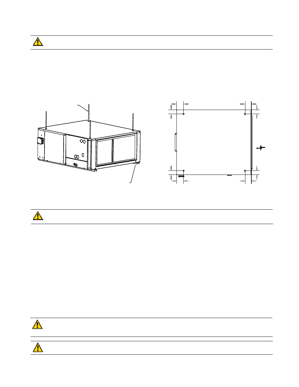
All air handler units are agency listed for horizontal installation with zero inches clearance to combustible materials. This
includes the unit cabinet, discharge plenum and connecting ducts. The unit can be floor mounted or suspended with
hanging rods. If hanging rods are used the unit has knockouts in each corner of the top and base panel for the suspension
rods to pass through. It is recommended that angle iron or unistrut be used under the unit for support when suspension
rods are used. Unit vibration isolators are recommended for all installations.
Flexible connections on the inlet and outlet duct connections of the unit are recommended.
3
Figure 1
SUSPENSION ROD
UNIT MOUNTING ANGLES
AIRFLOW
TOP VIEW
5
2 3/4
2 3/4
5
2 3/4
2 3/4
4 1/2
4 1/2