First Co WH / XH Horizontal Double wall User Manual
Page 6
6
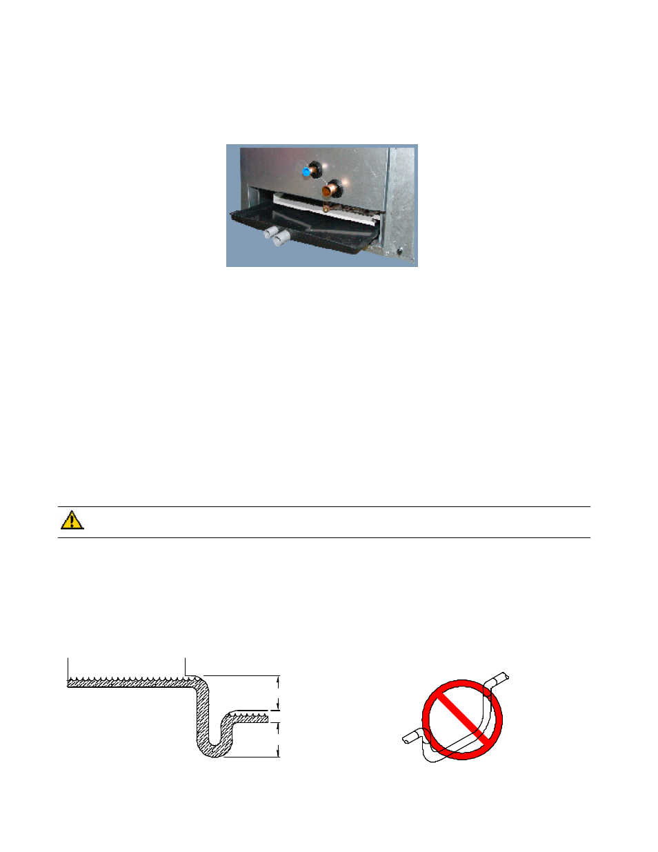
PROCEDURE 6 – DRAIN PAN
Drain pans have a 3/4 in primary and a 1/2 in secondary PVC coupling for condensate drain connection. Pans are designed
with positive slope to the drain couplings and can be removed from the unit for cleaning. To facilitate cleaning, unions
should be installed on the drain lines close to the drain pan coupling so the drain pan and drain pan door can be removed
together. See figure 2.
For drain pan removal refer to the maintenance section.
NOTE:
If unit is located in or above a living space where damage may result from condensate overflow, a field-supplied
external condensate pan should be installed underneath the entire unit, and a secondary condensate line (with appropriate
trap) should be run from the unit into the pan. Any condensate in this external condensate pan should be drained to a
noticeable place. As an alternative to using an external condensate pan, some localities may allow the use of a separate
condensate line (with appropriate trap) to a place where the condensate will be noticeable. The owner of the structure must
be informed that when condensate flows from the secondary drain or external condensate pan, the unit requires servicing, or
water damage will occur.
PROCEDURE 7 – CONDENSATE DRAIN
Units are equipped with a 3/4 in primary and a 1/2 in secondary PVC coupling for condensate drain connection. Condensate
drain lines must be installed with adequate slope away from the unit to assure positive drainage. Drain lines and traps
should run full size from the drain pan connection. The drain lines must have a properly designed trap. The trap depth and
distance between the trap outlet and the drain pan outlet should be twice the static pressure in the drain pan section under
normal operation for the trap to remain sealed. See figure 3. Prime all traps, test for leaks, and insulate traps if located
above a living area.
CAUTION:
Shallow running traps are inadequate and DO NOT allow proper condensate drainage. See
figure 4. Failure to follow this CAUTION could result in product and property damage.
NOTE:
If a Condensate Overflow Shut-off Switch, that is designed to be installed in the drain line, is used in place of a
secondary drain line, then the cut-off switch should be located in the primary drain line between the unit and the P-trap.
NOTE:
Condensate drain lines should be pitched downward at a minimum of 1 in. for every 10 ft. of length. Consult local
codes for additional restrictions or precautions.
DO NOT USE SHALLOW RUNNING TRAPS !
Figure 4 - Insufficient Condensate Trap
Figure 3 - Recommended Condensate Trap
Pressure P (inH2O)
at the drain pan
2P
2P
Figure 2 - Drain Pan with access door removed