Flowserve MP1 Sier-Bath User Manual
Page 16
MP1 USER INSTRUCTIONS ENGLISH 26999958
– 10-12
Page 16 of 48
flowserve.com
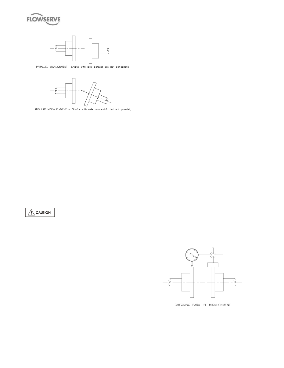
Figure 2
– Parallel and angular misalignment
The importance of accurate alignment of pump and
driver shafts cannot be overemphasized.
IMPROPER ALIGNMENT IS THE PRIMARY CAUSE
OF VIBRATION PROBLEMS AND REDUCED
BEARING LIFE.
A flexible coupling is used to compensate for slight
changes in alignment which occur during normal
operation and is not used to correct for installation
errors. Install the pump and driver half couplings in
accordance
with
the
coupling
manufacturer's
instructions. Note that the coupling hub faces are not
always mounted flush with the ends of the shafts.
Place the driver on the baseplate such that the correct
spacing is obtained between the two half couplings.
CHECK IF THERE IS A NEED TO SET
THE ELECTRIC MOTOR MAGNETIC CENTER AND
THE AXIAL ALIGNMENT BEFORE PROCEEDING
WITH
ANY
PARALLEL
AND
ANGULAR
ALIGNMENT. FAILURE TO DO SO MIGHT POSE
SERIOUS RISKS TO THE RELIABLE OPERATION
OF THE PUMP.
In the case of high power electric motors having sleeve
bearings, it might be necessary to run the motor to
establish the rotor magnetic center before defining the
axial setup of the pump. Consult the manufacturer's
instruction manual of the motor for additional details.
The purpose of the alignment procedure is to ensure
that there is no axial hunt/thrust nor eccentricity that
might create unbalance, between the driver shaft
(electric motor, gearbox, hydraulic power transmitter,
vapour/gas turbine, engine, etc.) and the pump shaft
that might affect or jeopardize the coupling mechanical
performance, and that both shafts are in parallel and
angular alignment under the normal operating
conditions of load and temperature (See Figure 2).
When the pump coupling and driver are assembled at
the factory, the units are aligned prior to shipment.
However, baseplates can be sprung or distorted during
shipment or installation and the alignment must be
checked before the unit is put in service. The coupling
spacer must be removed to make this check.
For pumps and drivers which operate at different
temperatures compensation must be made at the initial
alignment stage (when the units are at the same
temperature) to allow for thermal expansion during
operation. Consult the instruction manual supplied with
the driver for the manufacturer's recommendations.
Shaft alignment is greatly simplified by the use of a dial
indicator with extension rods and a magnetic base, or
using laser alignment devices. Before taking readings,
ensure that the pump and driver mounting bolts are
secure, and that the thrust bearing housing is properly
aligned in the bearing frame or cartridge. (See Section
6 MAINTENANCE).
Parallel Alignment:
Mount the magnetic base on the pump half coupling
hub (either the face or the O/D as shown in the sketch)
and place the dial indicator button on the outside
diameter of the driver half coupling hub. (See Figure
3).
Note that the length of extension rods should be kept
at a minimum to reduce deflection. Rotate the pump
shaft and record the dial reading at the top, bottom and
each side. Correct the parallel alignment by adding or
removing shims under the driver and/or moving the
driver horizontally.
Figure 3
– Parallel Misalignment
Repeat this procedure until the maximum Total
Indicator Reading (T.I.R.) is within 0.076 mm (0.003
in.).