2 handling, 3 lifting – Flowserve WUC Worthington User Manual
Page 12
WUC USER INSTRUCTIONS ENGLISH - 07/14
Page 12 of 52
2.0 TRANSPORT AND STORAGE
2.1 Consignment receipt and unpacking
Immediately after receipt of the equipment it must be
checked against the delivery and shipping documents
for its completeness and that there has been no
damage in transportation.
Any shortage and or damage must be reported
immediately to Flowserve and received in writing
within one month of receipt of the equipment. Later
claims cannot be accepted.
Check any crates, boxes and wrappings for any
accessories or spare parts which may be packed
separately with the equipment or attached to side
walls of the box or equipment.
Each product has a unique serial number. Check that
this number corresponds with that advised and
always quote this number in correspondence as well
as when ordering spare parts or further accessories.
2.2 Handling
Boxes, crates, pallets or cartons may be unloaded
using fork lift vehicles or slings dependent on their
size and construction.
2.3 Lifting
To avoid distortion, the pump unit should be
lifted as shown.
For lifting the driver refer to the
dimension drawing of driver.
2 holes Ø 45mm (1.77 in.) for
lifting the pump without can
and driver
4 pieces lifting screw
according DIN 580 only for
CAN lifting
Depending on the pump
size the pump unit is
packed separately from the
Can, or is put partially into
the Can.
A crane must be
used for all pump sets in
excess of 25 kg (55 lb).
Fully trained personnel
must carry out lifting, in
accordance with local
regulations. The driver and
pump weights are recorded
on their respective nameplates.
In some cases the pumps are not
complete assembled (refer to section 4, Installation).
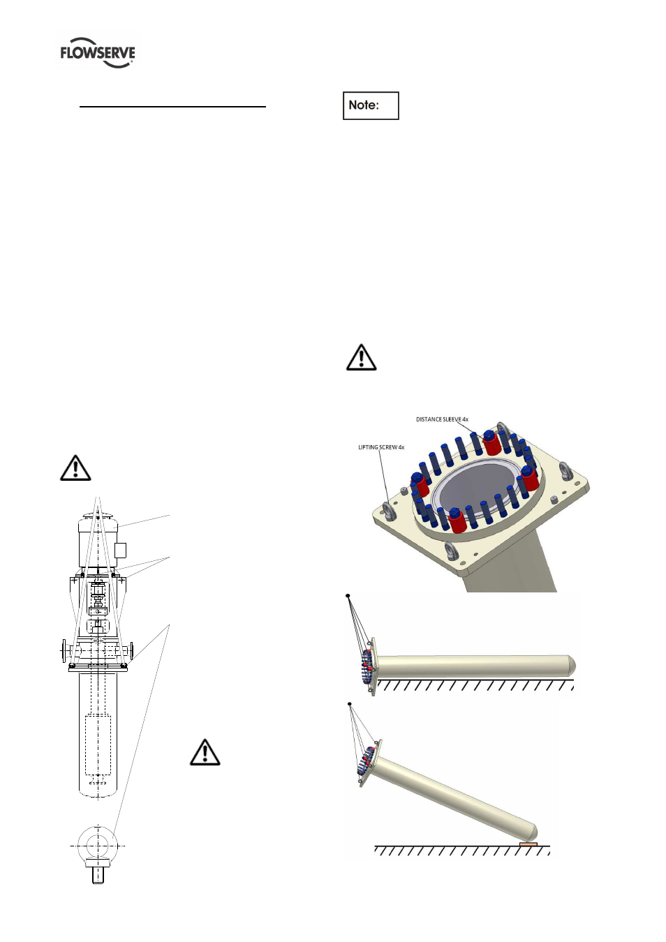
If Can and supporting flange are delivered
separately, lifting shall be performed as follows:
Suction barrel [1100.1] (also referred as ‘Can’) is
supplied together with supporting flange [6110] and
has to be installed into the sump first. Suction barrel
and supporting flange are delivered assembled
together. 4 distance sleeves are installed to fix both
parts together.
Install 4 lifting screws (also referred as ‘Eye Bolts’) on
the supporting flange and attach slings and straps to
bring the suction barrel to a vertical position. Move
the barrel for installation. Provide hand support to
prevent the suction barrel from swaying during
movement.
Distance sleeves are only used for fixing the
base plate during transportation.