4 initial alignment – Flowserve WUC Worthington User Manual
Page 18
WUC USER INSTRUCTIONS ENGLISH - 07/14
Page 18 of 52
[1350.1] also the intermediate shafts [2120.2] are
different from the intermediate shafts [2120.1].
With the rising main column pipe [1350.1] the top
shaft [2130.1] is assembled. Now you can put on the
headstock [1141] and hexagon head bolt [6577.4] it
to the top column pipe.
Tight the flange bolts crosswise by using a torque
wrench. (For torques refer to section 6, Maintenance)
4.4 Initial alignment
The adjustment of motor and pump must be checked
(if necessary, make a new adjustment) before first
start up of the unit.
The motor flange is equipped with adjustment-screws
on the motorstand. (Values for adjustment are
specified in the coupling instruction manual).
Ensure pump and driver are isolated electrically and
the half couplings are disconnected.
Align the motor to the pump, not the pump to the
motor. Alignment of the motor is achieved by using
the adjustment screws.
If the pump is equipped with a
hydrodynamic thrust bearing, pump shaft shall be
centered in the thrust pot prior to driver alignment
(refer to “Pump alignment for hydrodynamic thrust
bearings”). Pump shaft has to remain in the centered
position until the pump and driver shafts alignment is
completed.
4.4.1 Permissible misalignment limits at working
temperature
When checking parallel alignment, the total indicator
read-out (TIR) shown is twice the value of the actual
shaft displacement.
The pump is only pre-aligned! Carefully check
and readjust alignment before start of the unit.
Take out the spacer of the coupling and check the
alignment of shafts end of pump and driver. The
maximum parallel offset should not exceed 0.05 mm
(0.002 in.) and the axially offset can be ± 2.5 mm
(0.10 in.). The coupling spacer gap length shall be ±
0.25 mm (0.01 in.).
For more details refer to the manufacturer’s
instruction manual of coupling.
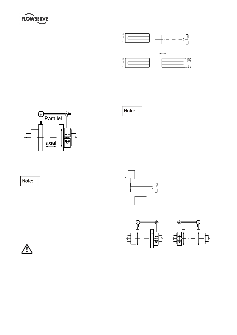
a)
b)
a) Parallel Offset: The median lines run parallel. The
maximum allowable parallel offset depends on
the size of coupling and is indicated in the
instruction manual of manufacturer of coupling
b) Axially Offset: Another offset is the displacement
of one or both of the shafts. A typical example is
thermal expansion.
The DBSE (distance between shaft ends)
is shown on the General Arrangement Drawing and is
larger than the length of the coupling spacer. This is
necessary to compensate all manufacturing
tolerances of line shafts and column pipes and to
allow correct axial adjustment of the rotor (refer to
5.3.1 Adjusting of the rotor).
For installation of the coupling spacer the coupling
hub on the pump shaft must be axially moved to
match the spacer. This results in an axial clearance
"x" between coupling hub and shaft end, which is
taken into account by the coupling selection.
How the alignment of the coupling should be done
you can see on the sketches and explanations below!
a)
b)
a) Fix the dial gauge on the driven shaft and check
the concentricity by turning of both hubs; correct it
if necessary.
b) Fix the dial gauge on the driving shaft and check
the concentricity by turning of both hubs; correct it
if necessary.
If the pump is handling hot liquid, the alignment must
be rechecked in warm condition of the unit.