8 examination of parts – Flowserve WUC Worthington User Manual
Page 40
WUC USER INSTRUCTIONS ENGLISH - 07/14
Page 40 of 52
Pull off the bearing housing [3200]. Loose the
studs [6572.2] and pull off the mechanical seal
cartridge.
To disassemble only the hydraulic
section start with point 11.
8) Open the hexagon head bolts [6577.4] and
disconnect the first column pipe from the
headstock [1141].
9) Pull out the complete bowl assembly together with
shafts and column pipes. Disconnect the first
column pipe.
10) Open the socket head cap screws [6579.2] and
slip upwards the shaft coupling [7020]. Remove
the coupling shell splits [7240]. Now the shafts are
uncoupled and you can proceed the same way
with the next column pipe until the bowl assembly
can be disconnected from the top or intermediate
shaft [2130.1 or 2120.1].
For 20 WU pump the pump shaft
[2110] is especially coupled to the first
intermediate shaft [2120.2] by a screwed
coupling. Unscrew the intermediate shaft [2120.2]
from the coupling sleeve [7250]. Now unscrew
the coupling sleeve [7250] from the pump shaft
[2110].
Both shafts have a left hand thread.
11) Open the hexagon head bolts [6577.7] and pull off
the suction casing [1130].
Take care of the O-ring [4610.5].
12) Remove the circlip [6544.2] and pull off the
impeller [2200.1].
If the pump is fitted with an inducer
[2215], it has to be pulled off instead of the
spacer sleeve.
13) Remove now the key [6700.3] and the next
retaining ring.
14) Open the hexagon head bolts [6577.7] and pull
off the pump bowl [1170.1], so you have access
to the next stage impeller.
Take care of the O-ring [4610.5].
15) Repeat step 12,13 and 14 until you reach the last
stage.
16) Open the hexagon head bolts [6577.6], which
connects the column pipe with the last pump
bowl [1170.2] and remove it.
Pull off the second intermediate bearing sleeve
[3400.2] from the pump shaft [2110].
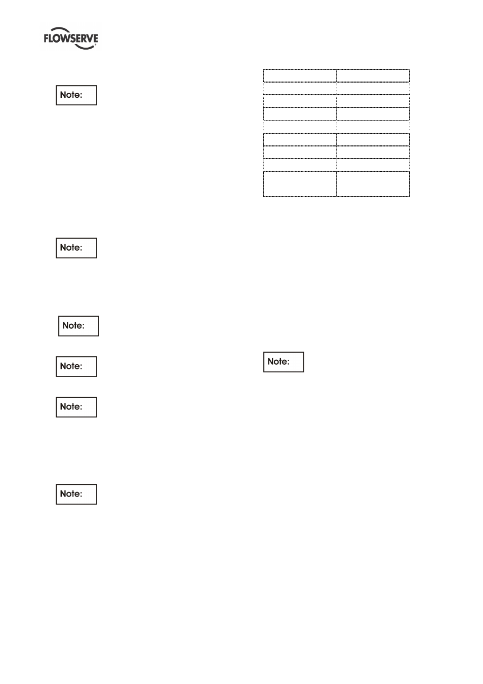
6.7.5 Dismantling of the thrust bearing
Thrust bearing No.
Bearing size
0 N
7210 BECBJ (M)
1 N
7313 BECBJ (M)
3 N
7315 BECBJ (M)
4 N
7317 BECBJ (M)
5 N
7318 BECBJ (M)
6 N
7322 BECBM
7 N
7326 BCBM
8 N
7232 BCBM
7330 BCBM
6.7.5.1 Bearing housing 3N – 8N
1) Remove the bearing assembly consisting of the
thrust ball bearing [3013.1], bearing adaptor
sleeve [2471], spacer ring [2510] and the bearing
lock nut [3712] as a cartridge.
2) Open the bearing lock nut [3712] and pull off the
thrust ball bearing [3013.1]
6.7.5.2 Bearing housing 0N – 1N
1) Remove the bearing assembly consisting of the
thrust ball bearing [3013.1], bearing adaptor
sleeve [2471] and the bearing lock nut [3712] as
a cartridge.
2) Open the bearing lock nut [3712] and pull off the
thrust ball bearing [3013.1].
For the hydrodynamic thrust bearing
dismantling, refer to bearing manufacturer´s IOM.
6.8 Examination of parts
1) Check the intermediate bearing sleeves and
bushings against any wear. The diametrical
clearance between sleeves and bushings must
not exceed twice the value in new condition.
2) Check the casing wear ring and the impeller wear
ring against any wear. The diametrical clearance
between the rings must not exceed twice the
value in new condition.
3) Check all parts against corrosion and erosion.
4) Carefully check the coupling against any wear.
5) Rotate the angular contact bearing by hand, to
check against abnormal sound. Check the
bearing cages against any wear and the outer
and inner race against running marks. Check the
runout of the shafts. TIR (Total Indicated Runout)
shall not exceed 0.04 mm/m (0.0005 in./ft) of
length. TIR shall not exceed 0.08 mm (0.003 in.)
over total shaft length.