3 impeller clearance – Flowserve WUC Worthington User Manual
Page 30
WUC USER INSTRUCTIONS ENGLISH - 07/14
Page 30 of 52
5.2.16 Lubrication
The bearing housing shall be filled with proper
lubricating oil prior to start up. If the pump will be
started after a longer storage period, the bearing
housing should be first flushed and cleaned with
gasoline. It is not necessary to remove the
preservation oil as this will mix up thoroughly with the
lubrication oil.
Lubrication is provided by the pumping effect of the
rotating ball bearings. Maintaining the correct oil level
(middle of the oil sight glass) ensures that the lower
ball bearing is covered with oil.
For recommended lubricating oils refer to the
lubrication table 5.2.7.
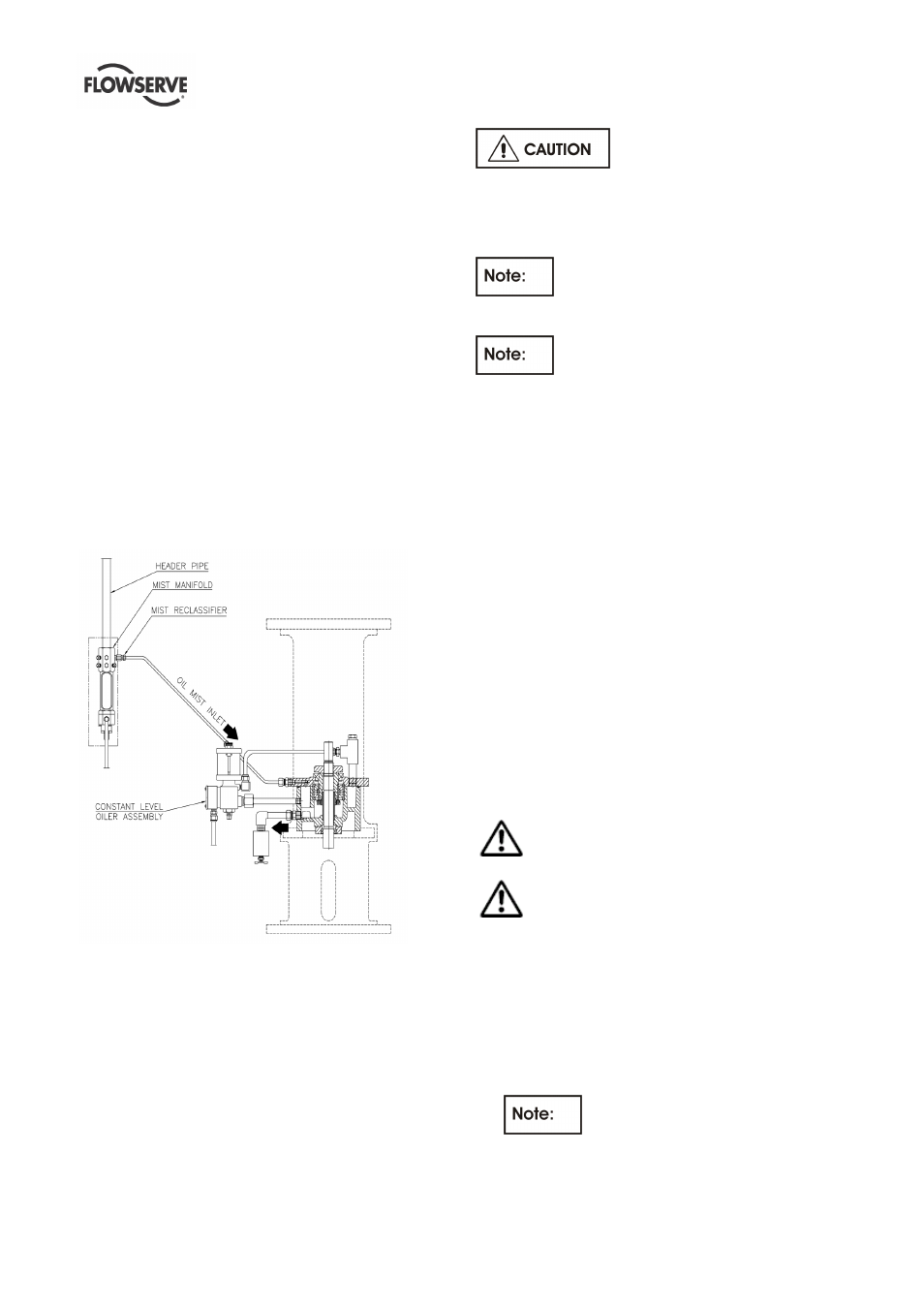
5.2.17 Purge oil mist Lubrication
Purge oil mist system utilize a continuous oil mist flow
through the bearing housing to deliver clean oil
directly to the bearing housing to maintain an outward
flow of air from the housing to prevent the ingress of
moisture and other corrosive contaminants.
The supplied air must be dry and clean. The
cleanness must be < 5µm.
For Purge Oil Mist Lubrication, a Reclassifier with a
Value of 0.09 SCFM should be used at the Manifold.
The bearing housing is equipped with a constant
level oiler with included overflow device. The
Overflow connection (3/8” tube) shall be connected to
a collection container.
Check overflow setting as per Oiler IOM.
The pressure in the bearing housing shall be 0,05
bar (0,74 psi) (20 inches of water column). A
continuous oil mist lubrication should be occur
during operation and stand by.
After start up the bearing temperature
must be observed carefully. The temperature at the
bearing housing should not exceed 85°C.
Refer to the GA-drawing regarding the
connections to the supply systems.
5.2.18 Oil change
After first start up, the oil shall be changed after 200
service hours.
Every further oil change shall take place after about
2000 service hours or at least every 6 month.
To change the oil use the following procedure:
a) Open the oil drain on the bearing housing to remove
the oil.
b) Close the oil drain and fill in Oil through the vent
connection on the bearing cover until the oil level
reaches the middle of the sight glass.
c) Fill the reservoir of the constant level oiler.
d) If necessary, the oil level can be adjusted by
referring to section 5.2.4 Oil level.
5.2.19 Oil level
The correct oil level is in the middle of the oil sight glass
and shall be checked when pump is not in operation.
Periodically check if the lubricating oil is mixed with any
condensed water. Careful opening of the oil drain
during a stop of the pump will show any water.
During operation a small increase of the oil level
can occur due to the oil mist supply.
A too high oil level will result in higher bearing
temperatures and therefore poorer lubrication.
5.3 Impeller clearance
Correct axial rotor setting is essential for trouble free
operation of the pump.
5.3.1 Adjusting of the rotor
a) Remove coupling spacer, coupling hub on pump
shaft and fan [8161] (when delivered).
Use an anaerobic adhesive for
securing the socket set screw for reassembly.
b) Fix the position of the mechanical seal by putting
the assembly jigs, mounted on the seal end plate,
into the groove in the shaft sleeve.