Flowserve L Worthington Simpson User Manual
Page 11
L and U USER INSTRUCTIONS ENGLISH 85392721 07-12
Page 11 of 36
flowserve.com
3
PUMP DESCRIPTION
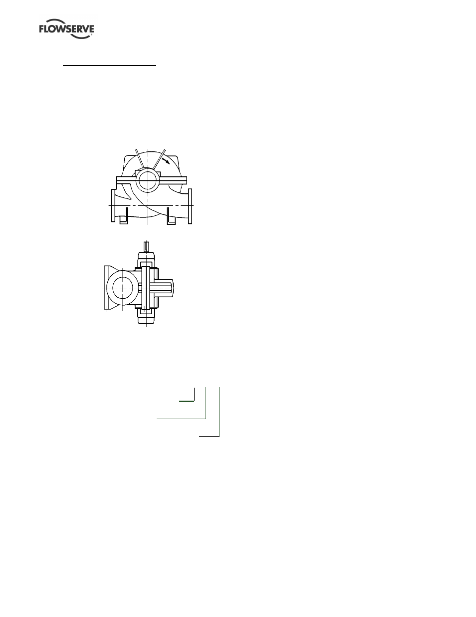
3.1 Configurations
The L and U range of pumps are horizontal split casing
volute type centrifugal pumps designed for water works,
drainage, general service and circulating applications.
They can be used with motor, steam turbine and
gasoline or diesel engine drives.
The range can have the following configurations:
L single-stage horizontal suction and discharge nozzles.
U two-stage horizontal suction and discharge nozzles.
LV single-stage horizontal suction/discharge, vertical shaft.
UV two-stage horizontal suction/discharge, vertical shaft.
3.2 Name nomenclature
The pump size will be engraved on the nameplate
typically as below:
6 L-13
Nominal discharge branch size (inch)
Configuration – see 3.1 above
Nominal maximum impeller diameter (inch)
The typical nomenclature above is the general guide
to the configuration description. Identify the actual
pump size and serial number from the pump
nameplate. Check that this agrees with the
applicable certification provided.
3.3 Design of major parts
3.3.1
Pump casing
The pump has its main casing gasket axial to the
shaft allowing maintenance to the rotating element by
removing the top half casing. Suction and discharge
branches are in the bottom half and therefore remain
undisturbed.
3.3.2
Impeller
The impeller is fully shrouded and may be fitted with
optional hub rings.
3.3.3
Shaft
The large diameter stiff shaft, mounted on bearings,
has a keyed drive end.
3.3.4
Pump bearings and lubrication
Ball bearings are fitted and are grease lubricated as
standard. There is an option of oil lubrication when
the pump is intended for horizontal mounting.
Bearing isolators or stationary labyrinths may be fitted
as an option in the bearing covers to protect the
bearings.
Vertically built pumps have as standard has a liquid
lubricated journal bearing fitted at the non-drive end.
This bearing is lubricated by pumped product or from
an external clean source.
3.3.5
Bearing housing
Two grease nipples enable grease lubricated bearings
to be replenished between major service intervals.
3.3.6
Seal housing
The design enables one of a number of sealing
options to be fitted.
3.3.7
Shaft seal
The mechanical seal(s), attached to the pump shaft, seals
the pumped liquid from the environment. Gland packing
may be fitted as an option on the L and U.
3.3.8
Driver
The driver is normally an electric motor. Different drive
configurations may be fitted such as internal combustion
engines, turbines, hydraulic motors etc driving via
couplings, belts, gearboxes, drive shafts etc.
3.3.9
Accessories
Accessories may be fitted when specified by the
customer.