Flowserve L Worthington Simpson User Manual
Page 15
L and U USER INSTRUCTIONS ENGLISH 85392721 07-12
Page 15 of 36
flowserve.com
Type and
size
Maximum forces (F) in N (lbf) and maximum moments (M) in Nm (lbf•ft)
Suction
Discharge
Fx
Fy
Fz
Mx
My
Mz
Fx
Fy
Fz
Mx
My
Mz
3L2
3680
(826)
2880
(648)
2100
(472)
2120
(1563)
1120
(826)
1500
(1106)
1540
(346)
1760
(396)
1280
(288)
880
(649)
480
(354)
640
(472)
3L13
2940
(661)
2310
(519)
1680
(378)
1700
(1254)
900
(664)
120
(885)
1540
(346)
1760
(396)
1280
(288)
880
(649)
480
(354)
640
(472)
4L13
4410
(991)
3470
(779)
2520
(566)
2550
(1880)
1350
(996)
1800
(1327)
1920
(432)
2200
(495)
160
(360)
1100
(811)
600
(442)
800
(590)
6L3
5880
(1322)
4620
(1039)
3.36
(755)
3400
(2507)
1800
(1327)
2400
(1770)
2880
(648)
3300
(742)
2400
(540)
1650
(1217)
900
(664)
1200
(885)
6L11
5880
(1322)
4620
(1039)
3.36
(755)
3400
(2507)
1800
(1327)
2400
(1770)
2880
(648)
3300
(742)
2400
(540)
1650
(1217)
900
(664)
1200
(885)
6L13
5880
(1322)
4620
(1039)
3.36
(755)
3400
(2507)
1800
(1327)
2400
(1770)
2880
(648)
3300
(742)
2400
(540)
1650
(1217)
900
(664)
1200
(885)
2U13
2350
(529)
1850
(415)
1340
(302)
1360
(1003)
720
(531)
960
(708)
1030
(230)
1170
(263)
850
(192)
590
(431)
320
(235)
430
(314)
3U15
3680
(826)
2880
(648)
2100
(472)
2120
(1563)
1120
(826)
1500
(1106)
1540
(346)
1760
(396)
1280
(288)
880
(649)
480
(354)
640
(472)
4U13
4410
(991)
3470
(779)
2520
(566)
2550
(1880)
1350
(996)
1800
(1327)
1920
(432)
2200
(495)
160
(360)
1100
(811)
600
(442)
800
(590)
4U18
4410
(991)
3470
(779)
2520
(566)
2550
(1880)
1350
(996)
1800
(1327)
1920
(432)
2200
(495)
160
(360)
1100
(811)
600
(442)
800
(590)
6U18H
5880
(1322)
4620
(1039)
3.36
(755)
3400
(2507)
1800
(1327)
2400
(1770)
2880
(648)
3300
(742)
2400
(540)
1650
(1217)
900
(664)
1200
(885)
Notes:
1. F= External force, tensile or compression
M=External moment, cw or ccw
2. Forces and Moments may be applied simultaneously in any
direction.
3. Values apply to all materials.
4. Higher loads may be acceptable, if direction and magnitude of
individual loads are known, but these need written approval
from Flowserve.
5. Pumps must be on rigid foundations and baseplates fully
grouted.
6. .Pump/baseplate should not be used as pipe anchor. Suction
and discharge piping should be anchored as close as possible
to the pump flanges to reduce vibration and prevent strain on
the pump casing. Expansion joints are recommended. They
must be properly tied and located on the side of the pipe anchor
away from the pump.
7. The pump mounting bolt torques specified must be used to prevent
relative movement between the pump casing and baseplate. (See
section 6.6 Fastener Torques.) The bolt material must have a
minimum yield strength of 600 N/mm² (87 000 lb/in²).
4.6.3
Suction piping
a) The inlet pipe should be one or two sizes larger
than the pump inlet bore and pipe bends should
be as large a radius as possible.
b) Pipework reducers should be conical and have a
maximum total angle of divergence of 15 degrees.
c) On suction lift the piping should be inclined up
towards the pump inlet with eccentric reducers
incorporated to prevent air locks.
d) On positive suction, the inlet piping must have a
constant fall towards the pump.
e) Flow should enter the pump suction with uniform
flow, to minimize noise and wear. This is
particularly important on large or high-speed
pumps which should have a minimum of five
diameters of straight pipe on the pump suction
between the elbow and inlet flange. See section
10.3, Reference 1, for more detail.
f) Inlet strainers, when used, should have a net `free
area' of at least three times the inlet pipe area.
g) Do not install elbows at an angle other than
perpendicular to the shaft axis. Elbows parallel
to the shaft axis will cause uneven flow.
h) Except in unusual circumstances strainers are
not recommended in inlet piping. If considerable
foreign matter is expected a screen installed at
the entrance to the wet well is preferable.
i)
Fitting an isolation valve will allow easier
maintenance.
j)
Never throttle pump on suction side and never
place a valve directly on the pump inlet nozzle.
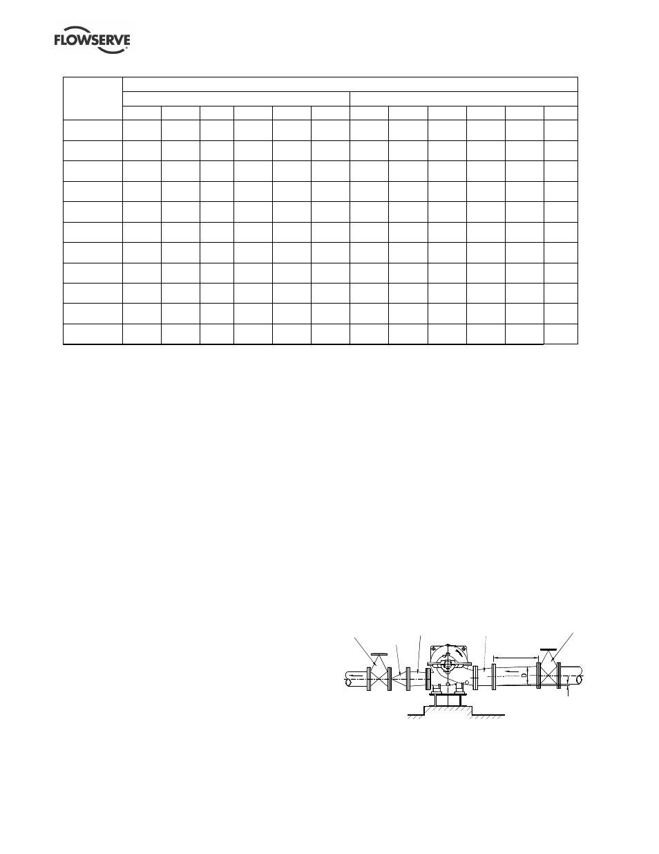
Typical design – flooded suction
Note:
Ideally reducers should be limited to one pipe diameter change,
i.e. 150 mm (6 in.) to 200 mm (8 in.). Must have a maximum total
angle of divergence of 15 degrees.
Non
return
valve
Concentric
conical
reducer
Eccentric
conical
reducer
>5D
Discharge
isolating
valve
Suction
isolating
valve
Slope up from
pump suction