4 performance and operating limits, 4installation, 1 location – Flowserve L Worthington Simpson User Manual
Page 12: 2 part assemblies, 3 foundation
L and U USER INSTRUCTIONS ENGLISH 85392721 07-12
Page 12 of 36
flowserve.com
3.4 Performance and operating limits
This product has been selected to meet the
specifications of your purchase order. See section 1.5.
The following data is included as additional information to
help with your installation. It is typical, and factors such
as temperature, materials, and seal type may influence
this data. If required, a definitive statement for your
particular application can be obtained from Flowserve.
3.4.1
Operating limits
Pumped liquid temperature limits*
- 20 to + 150 ºC
(- 4 to + 302 ºF)
Maximum ambient temperature*
- 20 to + 40 ºC
(- 4 to +104 ºF)
Maximum soft solids in suspension*
up to 3 % by volume
(refer for size limits)
Maximum pump speed
refer to the nameplate
*Subject to written agreement from Flowserve.
3.4.2
Pump and impeller data
Pump
size
Impeller
minimum
passage size
mm (in)
Nominal wear
ring diameter
mm (in)
Mean radial
wear ring
clearance
mm (in)
3L2
15 (0.59)
112.88 (4.44)
0.09 (0.003)
3L13
19 (0.75)
112.34 (4.42)
0.22 (0.009)
4L13
28.5 (1.13)
152.00 (5.98)
0.22 (0.009)
6L3
20 (0.78)
157.00 (6.18)
0.22 (0.009)
6L11
33 (1.31)
161.52 (6.36)
0.22 (0.009)
6L13
33 (1.31)
177.39 (6.98)
0.22 (0.009)
2U13
14 (0.55)
110 .00 (4.33)
0.16 (0.006)
3U15
14 (0.55)
152.00 (5.98)
0.23 (0.009)
4U13
16 (0.63)
190.00 (7.48)
0.20 (0.008)
4U18
20 (0.79)
190.00 (7.48)
0.20 (0.008)
6U18H
41 (1.61)
248.00 (9.76)
0.28 (0.011)
* May be up to 0.13 mm (0.005 in.) larger if casing ring and
impeller have a tendency to gall.
Clearances for non-metallic wear rings are
smaller, typically 50 - 65% of those for the standard
metallic rings shown above.
4
INSTALLATION
Equipment operated in hazardous locations
must comply with the relevant explosion protection
regulations. See section 1.6.4, Products used in
potentially explosive atmospheres.
4.1 Location
The pump should be located to allow room for
access, ventilation, maintenance and inspection with
ample headroom for lifting and should be as close as
practicable to the supply of liquid to be pumped.
Refer to the general arrangement drawing for the
pump set.
4.2 Part assemblies
Motors may be supplied loose on vertically mounted
pumps, typically on motor frame sizes 315 and
above. It is the responsibility of the installer to ensure
that the motor is assembled to the pump and lined up
as detailed in section 4.5.2, Alignment methods.
4.3 Foundation
There are many methods of installing
pump units to their foundations. The correct method
depends on the size of the pump unit, its location and
noise vibration limitations. Non-compliance with the
provision of correct foundation and installation may
lead to failure of the pump and, as such, would be
outside the terms of the warranty.
Ensure the following are met:
a) The baseplate should be mounted onto a firm
foundation, either an appropriate thickness of
quality concrete or sturdy steel framework.
(It should NOT be distorted or pulled down onto
the surface of the foundation, but should be
supported to maintain the original alignment.)
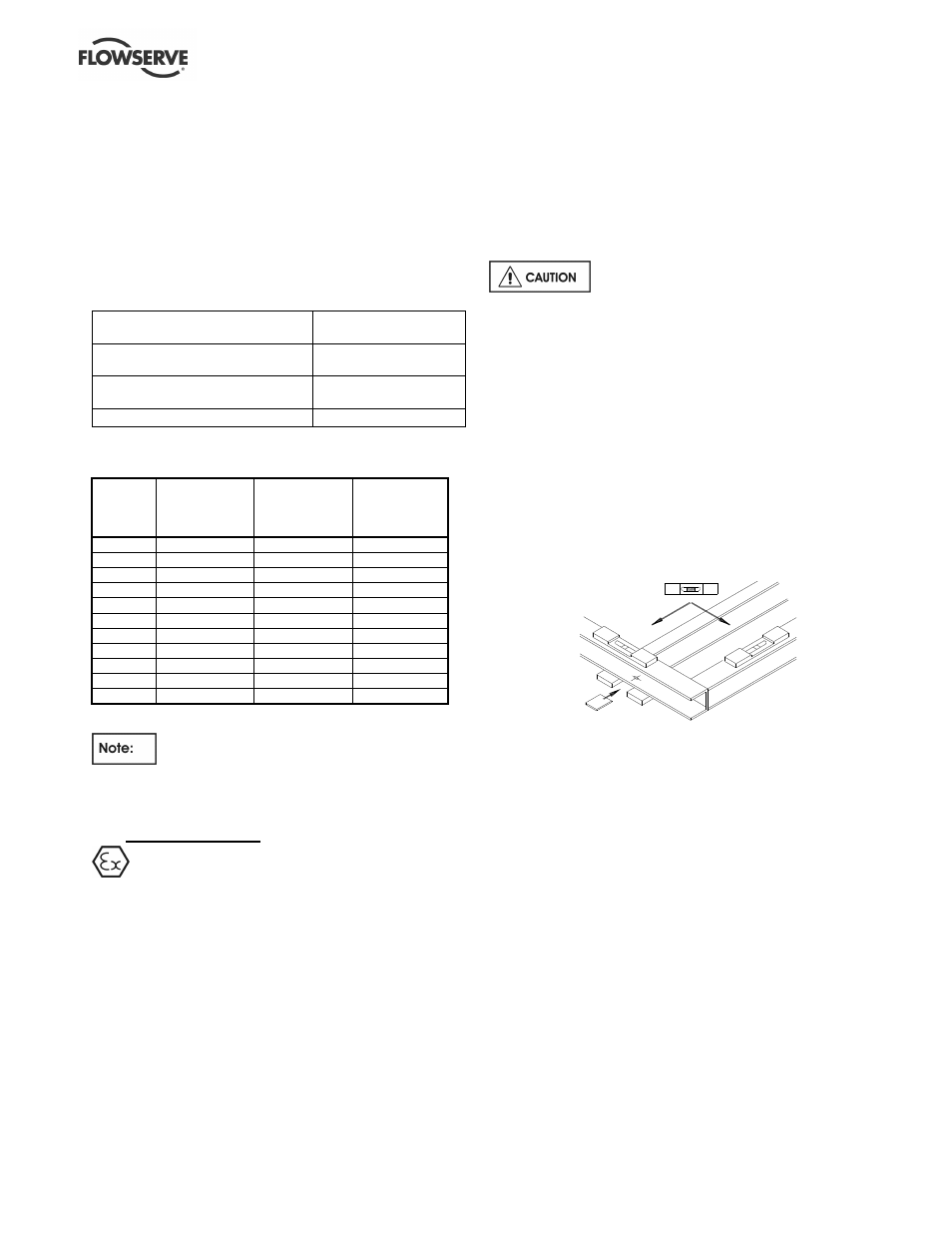
b) Install the baseplate onto packing pieces evenly
spaced and adjacent to foundation bolts.
c) Level with shims between baseplate and packing
pieces.
d) The pump and driver have been aligned before
dispatch however the alignment of pump and motor
half coupling must be checked. If this is incorrect, it
indicates that the baseplate has become twisted
and should be corrected by re-shimming.
e) Vertical pumps should be mounted following the
practices outlined for baseplate mounted pumps.
(Larger sizes may need the motor fitting after
installing the pump - refer to section 4.5.2.)
f) If the pump is driven via a universal joint drive
shaft there may be a requirement to offset the
pump shaft with respect to the driver to optimize
the universal joint drive
shaft bearing life. This
offset will typically be in the range 0 to 4 degrees
depending on shaft design. Please consult the
separate User Instructions before installation.
g) Any support for the universal joint drive
shaft
plummer blocks must not exhibit resonant
frequencies in the range 0.8 to 1.2 N where
N = pump running speed.