Flowserve L Worthington Simpson User Manual
Page 14
L and U USER INSTRUCTIONS ENGLISH 85392721 07-12
Page 14 of 36
flowserve.com
A button (screwed into one of the shaft ends) is
normally fitted between the motor and pump shaft
ends to fix the axial position.
If the motor does not run in its
magnetic centre the resultant additional axial force
may overload the pump thrust bearing.
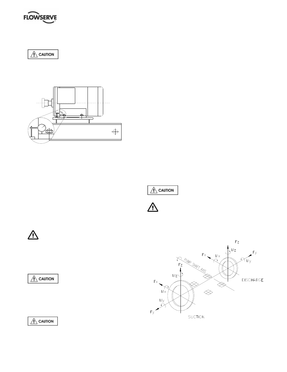
4.5.3
Check for soft foot
This is a check to ensure that there is no undue
stress on the driver holding down bolts; due to non-
level baseplate or twisting. To check, remove all
shims and clean surfaces and tighten down driver to
the baseplate. Set a dial indicator as shown in the
sketch and loosen off the holding down bolt while
noting any deflection reading on the dial test indicator
- a maximum of 0.05 mm (0.002 in.) is considered
acceptable but any more will have to be corrected by
adding shims. For example, if the dial test indicator
shows the foot lifting 0.15 mm (0.006 in.) then this is
the thickness of shim to be placed under that foot.
Tighten down and repeat the same procedure on all
other feet until all are within tolerance.
Complete piping as below and see sections 4.7,
Final shaft alignment check up to and including
section 5, Commissioning, start-up, operation and
shutdown before connecting driver and checking
actual rotation.
4.6 Piping
Protective covers are fitted to the pipe
connections to prevent foreign bodies entering during
transportation and installation. Ensure that these
covers are removed from the pump before connecting
any pipes.
4.6.1
Suction and discharge pipework
Never use the pump as a support for
piping.
In order to minimize friction losses and hydraulic
noise in the pipework it is good practice to choose
pipework that is one or two sizes larger than the
pump suction and discharge. Typically main
pipework velocities should not exceed 2 m/s (6 ft/sec)
suction and 3 m/s (9 ft/sec) on the discharge.
Take into account the available NPSH which must be
higher than the required NPSH of the pump.
Maximum forces and moments allowed on the pump
flanges vary with the pump size and type. To minimize
these forces and moments that may, if excessive,
cause misalignment, hot bearings, worn couplings,
vibration and the possible failure of the pump casing,
the following points should be strictly followed:
•
Prevent excessive external pipe load
•
Never draw piping into place by applying force to
pump flange connections
•
Do not mount expansion joints so that their force,
due to internal pressure, acts on the pump
flange. It is recommended that expansion joints
use threaded rod to limit any forces of this type
The table in 4.6.2 summarizes the maximum forces
and moments allowed on horizontal shaft pump
casings. Refer to Flowserve when the pump shaft is
vertical.
Ensure piping and fittings are flushed
before use.
Ensure piping for hazardous liquids is arranged
to allow pump flushing before removal of the pump.
4.6.2
Maximum forces and moments allowed on
the pump suction and discharge flanges
of horizontal shaft pumps
See table overleaf.