Flowserve Polybase baseplates User Manual
Page 12
Polybase Baseplate INSTRUCTIONS ENGLISH 71569284 – 12-10
Page 12 of 24
flowserve.com
practice is to confirm in our shop that the pump
assembly can be accurately aligned. Before
shipment, the factory verifies that there is enough
horizontal movement capability at the motor to
obtain a “perfect” final alignment when the installer
puts the baseplate assembly into its original, top
leveled, unstressed condition.
4.3.3
Stilt mounted Polybase baseplates
Flowserve offers a stilt mounted option for Polybase
baseplates (See Figure 4-5). The baseplate is set on
a flat surface with no tie down bolts or other means of
anchoring it to the floor.
General instructions for assembling these baseplates
are given below. For dimensional information, please
refer to the appropriate Flowserve “Sales Print.”
Note: The following assembly procedure should be
carried out as closely to the final installation location
as possible. DO NOT remove the Polybase from its
shipping pallet until it is in the area of the installation
and you are ready to assemble the stilts.
4.3.3.1
Stilt mounted baseplate assembly
instructions for 264 and shorter
Polybase baseplates (Refer to Figures 4-
3 and 4-5)
a) Raise or block up baseplate/pump above the
floor to allow for the assembly of the stilts.
b) Bolt the cross bars onto the underside of the
Polybase baseplate.
c) Predetermine or measure the approximate
desired height for the baseplate above the floor.
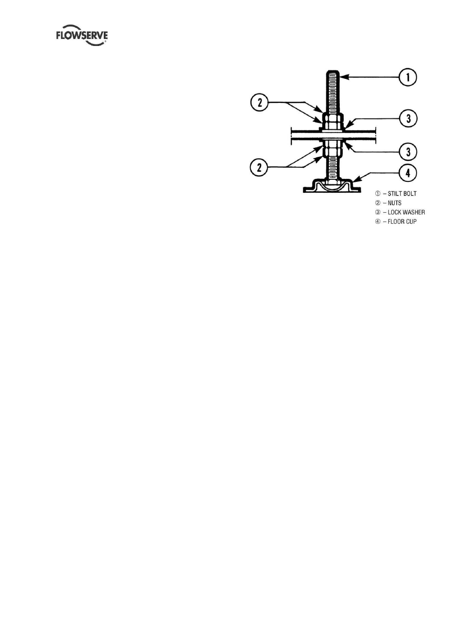
d) Set the bottom nuts (item 2) above the stilt bolt
head (item 1) to the desired height.
e) Assemble lock washer (item 3) down over the stilt
bolt.
f) Assemble the stilt bolt up through hole in the
cross bar and hold in place.
g) Assemble the lock washer (item 3) and nut (item
2) on the stilt bolt. Tighten the nut down on the
lock washer.
h) After all four stilts have been assembled, position
the baseplate in place, over the floor cups (item
4) under each stilt location, and lower the
baseplate to the floor.
i)
Level and make final height adjustments to the
suction and discharge pipe by first loosening the
top nuts and turning the bottom nuts to raise or
lower the baseplate.
j)
Tighten the top and bottom nuts at the lock
washer (item 3) first then tighten the other nuts.
k) It should be noted that the connecting pipelines
must be individually supported, and that the stilt
mounted baseplate is not intended to support
total static pipe load.
Figure 4.3