Flowserve Polybase baseplates User Manual
Page 13
Polybase Baseplate INSTRUCTIONS ENGLISH 71569284 – 12-10
Page 13 of 24
flowserve.com
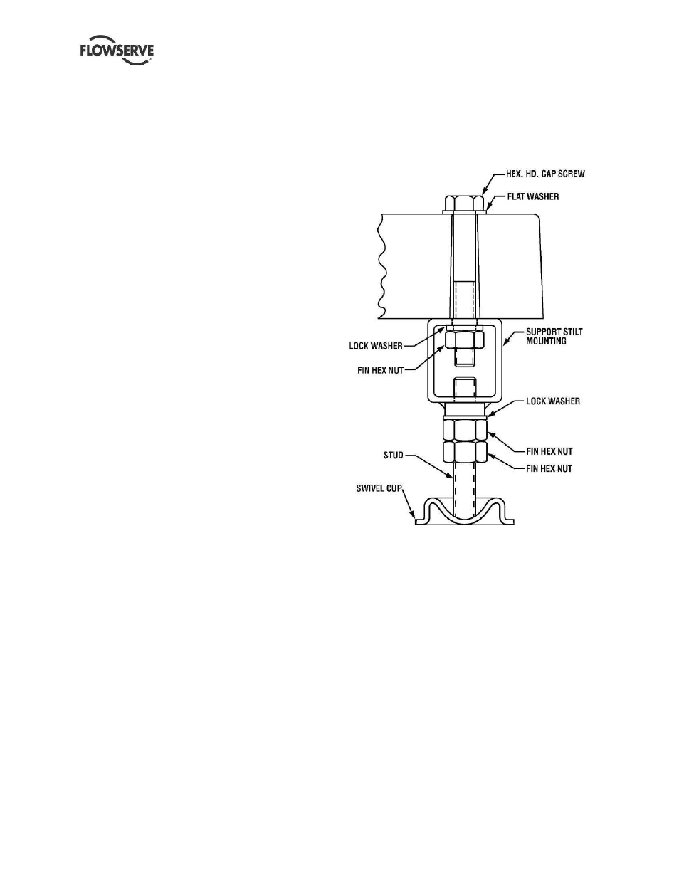
4.3.3.2
Stilt mounted baseplate assembly
instructions for 268 and longer Polybase
baseplates (Refer to Figures 4-4 and 4-5)
a) Determine or measure the approximate desired
height for the baseplate above the floor.
b) Sling and hoist the baseplate/pump assembly off
its shipping pallet in accordance with the
procedures shown in Section 2.3.
c) Bolt the stilt beams to the underside of the
Polybase using the fasteners provided as shown
in Figure 4.4. Torque the 7/8” bolts to 217Nm
(160 lbf*ft).
d) Thread two hex nuts onto each stud. Install one
internal-tooth lockwasher over the FLAT ends of
each stud. Thread the flat ends of the studs into
the weld nuts on the undersides of the
longitudinal support beams until the low point of
each SPHERICAL end is at the desired distance
from the bottom surface of the Polybase. Do not
tighten the nuts at this point.
e) After all four stilts have been assembled, position
the Polybase in place over the floor cups under
each stilt location, and GENTLY lower the
assembly to the floor.
f) Using two wrenches, lock the two hex nuts on
each stud together. Turn the studs by means of
these locked nuts to raise or lower the assembly.
When the desired leveling is achieved, unlock the
pairs of nuts and thread the upper ones (with
lockwashers on top) up until they make contact
with the weld nuts on the beams. Tighten
securely. Thread the lower nuts up and tighten to
lock the assembly in place.
g) Recheck levels and adjust if necessary.
h) It should be noted that the connecting pipe lines
must be individually supported, and that the stilt
mounted Polybase is not intended to support total
static pipe load.
4.3.3.3
Stilt mounted baseplates - motor
alignment
The procedure for motor alignment on stilt mounted
baseplates is similar to grouted baseplates. The
difference is primarily in the way the baseplate is
leveled.
a) Level the baseplate by using the stilt adjusters.
(Shims are not needed as with grouted
baseplates.) After the base is level, it is locked in
place by locking the stilt adjusters.
b) Next the initial pump alignment must be checked.
The vertical height adjustment provided by the
stilts allows the possibility of slightly twisting the
baseplate. If there has been no transit damage
or twisting of the baseplate during stilt height
adjustment, the pump and driver should be within
0.38 mm (0.015 in.) parallel, and 0.0025 mm/mm
(0.0025 in./in.) angular alignment. If this is not
the case, check to see if the driver mounting
fasteners are centered in the driver feet holes.
Figure 4.4
c) If the fasteners are not centered there was likely
shipping damage. Re-center the fasteners and
perform a preliminary alignment to the above
tolerances by shimming under the motor for
vertical alignment, and by moving the pump for
horizontal alignment.
d) If the fasteners are centered, then the baseplate
may be twisted. Slightly adjust (one turn of the
adjusting nut) the stilts at the driver end of the
baseplate and check for alignment to the above
tolerances. Repeat as necessary while
maintaining a level condition as measured from
the pump discharge flange. Lock the stilt
adjusters.
The remaining steps are the same as for new grouted
baseplates.