Flowserve Polybase baseplates User Manual
Page 15
Polybase Baseplate INSTRUCTIONS ENGLISH 71569284 – 12-10
Page 15 of 24
flowserve.com
4.4 Grouting
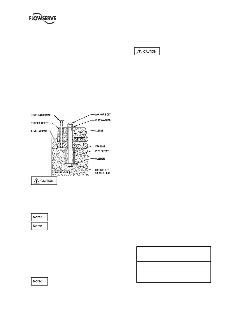
a) The pump foundation should be located as close
to the source of the fluid to be pumped as
practical. There should be adequate space for
workers to install, operate, and maintain the
pump. The foundation should be sufficient to
absorb any vibration and should provide a rigid
support for the pump and motor. Recommended
mass of a concrete foundation should be three
times that of the pump, motor and base. Refer to
Figure 4-6 for a cross-section of the
recommended foundation and baseplate
arrangement. Note that foundation bolts are
imbedded in the concrete inside a sleeve to allow
some movement of the bolt.
Figure 4.6
b)
Gently set the Polybase baseplate
down onto the foundation. Do not subject a
Polybase baseplate to heavy shock loading.
c) Level the pump baseplate assembly. The proper
surfaces to reference when leveling the pump
baseplate assembly are the pump suction and
discharge flanges.
DO NOT stress the baseplate.
DO NOT bolt the suction or discharge
flanges of the pump to the piping until the
baseplate grouting has been completed If
equipped, use leveling jackscrews to level the
baseplate. If jackscrews are not provided, shims
and wedges should be used. Check for
levelness in both the longitudinal and lateral
directions. Shims should be placed at all base
anchor bolt locations, and in the middle edge of
the base if the base is more than 1.5 m (5 ft)
long.
DO NOT RELY ON THE BOTTOM OF
THE POLYBASE BASEPLATE TO BE FLAT.
This is an as-molded surface which is not as flat
as the mounting (top) surface.
d) After leveling the baseplate, install flat washers
and nuts on the anchor bolts.
ENSURE THE NUTS HAVE A
SNUG FIT, BUT DO NOT TORQUE THEM AT
THIS POINT.
If shims are used, make sure to shim the
baseplate near each anchor bolt and snug the
nut firmly with a wrench. Failure to do this may
result in a twist of the baseplate, which could
make it impossible to obtain final alignment.
Check the level of the baseplate to ensure that it
was maintained, else adjust the jackscrews or
shims as needed until the baseplate is level
e) Check initial alignment. If the pump and motor
were removed from the baseplate, install them so
that prior to grouting it can be verified that
alignment can be achieved. If the pump and
motor were properly reinstalled to the baseplate
or if they were not removed from the baseplate
and there has been no transit damage, and also
if the above pre-grout steps where done properly,
the pump and driver should be within 0.38 mm
(0.015 in.) FIM (Full Indicator Movement) parallel,
and 0.0025 mm/mm (0.0025 in./in.) FIM angular.
If this is not the case, first check to see if the
driver mounting fasteners are centered in the
driver feet holes. If not, re-center the driver on its
fasteners and perform a preliminary alignment to
the above tolerances by shimming under the
motor for vertical alignment, and by moving the
pump for horizontal alignment.
f) Grout the baseplate. A non-shrinking grout
should be used. Make sure that the grout fills the
area under the baseplate. After the grout has
cured, check for voids and fill them if possible.
Jackscrews, shims and wedges should be
removed from under the baseplate at this time. If
they were to be left in place, they could rust,
swell, and cause distortion in the baseplate.
g) Lubricate the anchor bolt threads and torque the
nuts using a torque wrench to values noted in
table 4-1 below.
Table 4-1
Bolt size
Recommended
torque Nm (lbf ft)
lubricated
M12 & ½ in.
27(20)
M20 & ¾ in.
96 (70)
M22 &
7
/
8
in.
150 (110)
M24 & 1 in.
220 (160)