Flowserve Polybase baseplates User Manual
Page 18
Polybase Baseplate INSTRUCTIONS ENGLISH 71569284 – 12-10
Page 18 of 24
flowserve.com
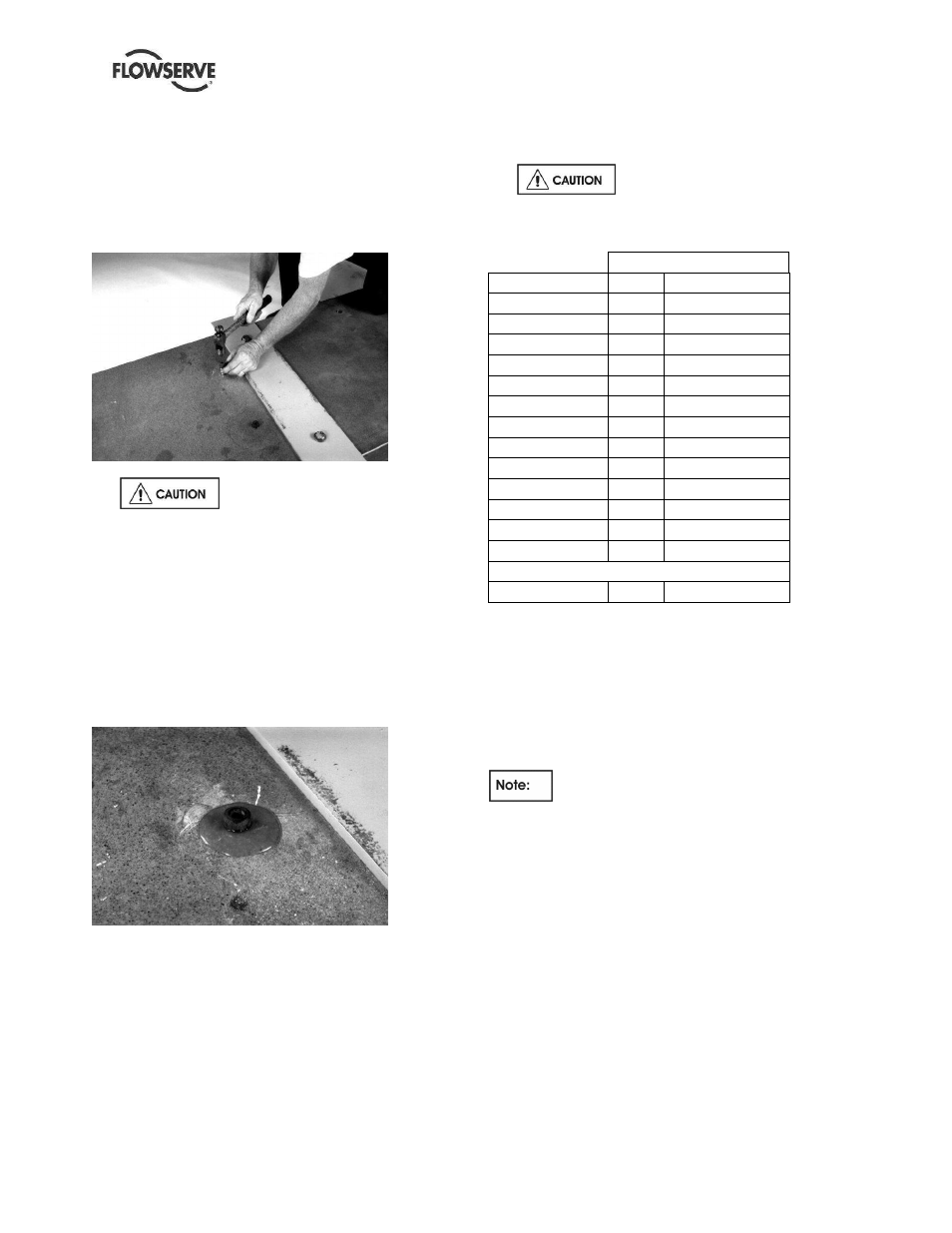
g) Engage the blind end of the stainless steel insert
in the hole. Tap on the cap screw head with light
hammer or soft mallet to drive the insert into the
hole (see Figure 6.3). Hold the insert straight
until it has been driven in to approximately half its
length; the insert is self-aligning once it has
passed this point.
Figure 6.3
h)
Drive the insert in slowly to give
the adhesive time to flow around the grooves in
the insert. Drive the insert in to the point where
its top surface is flush with or just below the
surface of the baseplate. Excess adhesive will
squeeze out and pool around the top of the insert
as shown in Figure 6.4. Do not remove this
excess material. As the adhesive cures, some of
this excess will draw down into the space
between the insert and the wall of the hole. Do
not remove the cap screw at this time.
Figure 6.4
i)
Allow the adhesive to cure undisturbed for 48
hours.
j)
Following cure remove the screw. Excess
adhesive may be chipped off with a putty knife. If
desired, lightly sand the surface of the baseplate
to a flat, smooth condition.
k) OPTIONAL. It is up to the user to decide if a
sample insert axial pullout test is needed using
torque values given in clause 6.6.
l)
The baseplate is now ready to be put back into
service. The equipment fasteners mounting
torques are given in clause 6.7 Table 6-3.
Do not exceed the maximum
torque value given in Table 6-3in relation to
fastener mechanical properties.
Table 6-1
Drill Diameter
Thread Size
mm
inches
5/16-18 UNC
18
45/64 (.703)
3/8-16 UNC
18
45/64 (.703)
M6
18
45/64 (.703)
M8
18
45/64 (.703)
M10
18
45/64 (.703)
1/2-13 UNC
21
53/64 (.828)
M12
21
53/64 (.828)
5/8-11 UNC
29
1-1/8 (1.125)
3/4-10 UNC
29
1-1/8 (1.125)
M16
29
1-1/8 (1.125)
M20
29
1-1/8 (1.125)
7/8-9 UNC
32
1-1/4 (1.250)
M24
32
1-1/4 (1.250)
Depth (all)
46
1-13/16 (1.81)
6.6 Field installed thread insert
testing (Optional)
If user elects to assess the validity of his installation
or replacement of thread inserts, here are provided
the necessary bolts torques for the axial pull-out
testing of the insert sample(s).
The torque values tabulated below are
maximums that the inserts in the Polybase baseplate
can withstand without any damage. These values
may exceed the material strength of the bolts being
used to do the test. The end user must consider the
type of bolt and lubrication used (if any) before
tightening.