Isc2 seal installation, Seal chamber requirements – Flowserve ISC2 Series User Manual
Page 10
10
5.8 Handle the ISC2 seal with care; it is manufactured to precise
tolerances. The seal faces are of special importance and
should be kept perfectly clean at all times.
5.9 Tools needed for installation: An open-end wrench and torque
wrench sized for the gland bolt nuts; a torque wrench for the
set screws. All other tools are provided.
6. ISC2 Seal Installation
The installation chamber for the mechanical seal must be checked
against the correspond ing drawing and table of dimensions.
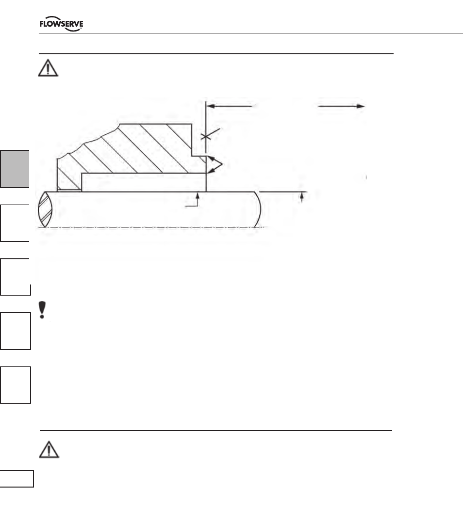
Shaft or sleeve finish to be 32 µ inch
(0.8 µm) Ra or better
• Bearings must be in good condition.
• Maximum lateral or axial movement of shaft (end play) = 0.010 inch ( 0.25 mm) FIM
• Maximum shaft runout at face of seal housing = 0.002 inch (0.05 mm) FIM
• Maximum dynamic shaft deflection at seal housing = 0.002 inch (0.05 mm) FIM
Seal housing bore to have
√125 µ inch (3.2 µm) Ra or better
Seal Chamber Requirements
The mechanical seal may be installed when there are no visible
signs of damage to the mechanical seal. This applies in particular to
the seats, centrings, and the statically sealing O-rings.
to first
obstruction
Face of seal housing to be square to the axis of the
shaft to within 0.0005 inch (0.013 mm) FIM and have
√63-µ Inch (1.6 µm) Ra finish or better.
Gland pilot can be either of these register locations.
Concentric to within 0.005 inch (0.13 mm) FIM of
shaft or sleeve OD
Shaft or sleeve OD
+0.000 inch (+ 0.000 mm)
-0.002 inch (- 0.050 mm) ANSI
+0.000 inch (+0.000 mm) API 610
-0.001 inch (-0.025 mm) DIN / ISO
Figure 1