6 setting device installation, 7 gland cap screw and retainer sleeve installation – Flowserve PSS III Durametallic User Manual
Page 9
9
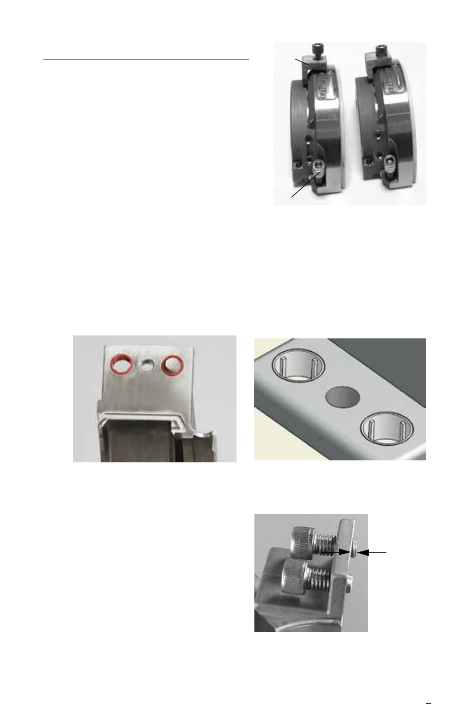
6 Setting Device Installation
6.1 Place the setting device over the
locating hole and secure with the
cap screw. See Figure 14.
6.2 Repeat this procedure for the
other seal drive half.
Figure 14
Figure 15
7.2 Lightly coat the gland cap screws
with anti-seize and thread them
through the retainer sleeves until
they protrude 1.27 to 2.03 mm
(0.050 to 0.080 inch) past the
gland joint. See Figure 17.
7.3 Repeat this procedure for the
other gland half.
1.27 -
2.03 mm
(0.050 -
0.080 inch)
Figure16
7 Gland Cap Screw and Retainer Sleeve Installation
7.1 One end of the retainer sleeve has a rib which is flush with the end
of the sleeve. The end with the exposed rib is positioned to the
machined side of the flange. Insert one retainer sleeve into each
clearance hole. See Figure 15 and 16.
Figure 17
Cap
Screw
Setting
Device