Flowserve XL90 Series User Manual
Page 10
1 Base assembly
2 Cover
3 Screw
6 Pressure gauge 0-160 psi
7 Bottom relay assembly
8 O-ring
9 Upper relay assembly
10 Orifice screw
11 O-ring
12 O-ring
13 Relay diaphragm assembly
14 Relay plate
15 Diaphragm retaining plate
16 Signal diaphragm assembly
17 Set screw
18 Spring
19 Set screw
20 Nut
21 Adjustable gain upper plate/flapper assembly
22 Pan head screw
23 Socket screw
24 Washer
25 Spacer nut
26 Adjustable gain lower plate
27 Poppet cover
28 Poppet
29 Poppet spring
30 O-ring
31 Retaining ring
32 Screw
33 Screw
34 Adjustable seat
35 Rubber cap
36 Balance adjust screw
37 O-ring
38 O-ring
39 Adjustable seat spring
40 Span arm
43 Pivot bushing
44 Pivot screw
45 Snap ring
46 Zero arm
47 Feedback spring
48 Pivot block
49 Adjust zero knob
50 Zero locking knob
48-10
Flowserve Corporation, Valtek Control Products, Tel. USA 801 489 8611
121
119
116
118
120
2
69
72
73
117
107
67
66
69
3
116
128
53
112
44
43
45
40
106
52
112
1
31
27
30
56
29
8
12
7
8
117
46
47
48
49
50
45
14
16
26
24
32
17
15
32
22
23
18
19 21
20
25 33
11
33
35
38
36
10
57
8
15
13
14 12
110
9
34
37
28
29
39
30 27
31
119
118
3
2
33
28
8
6
200
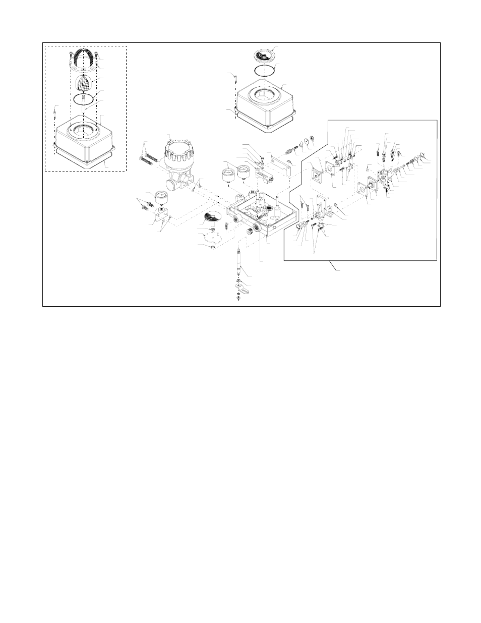
130
Figure 16: XL90 Positioner – Exploded View – Accord Cam
52 Cam shaft
53 Cam
55 Nut
56 Screw
57 O-ring
66 Pneumatic adapter
67 Screw
69 O-ring
72 I/P module
73 Screws
106 Washer
107 Signal gauge
110 Orifice screen
112 Snap ring
116 Rotor or indicator
117 O-ring
118 O-ring
119 Dome
120 Adapter shaft
121 Screw
128 Jam nut
130 Spring
200 Relay assembly
All of the above parts are in stock and can be purchased in a spare parts kit. For selecting and ordering the appropriate kit or a new positioner, contact your Flowserve
representative or the factory.