Flowserve XL90 Series User Manual
Page 5
4. Remove rubber cap over balance adjustment screw. (See
Figure 6.)
5. Apply full actuator operating pressure to positioner supply
port.
6. Set input signal to midscale (9 psi for 3-15 psi span).
Output pressure level cannot be adjusted with actuator
against valve seat or travel stops. Allow actuator pressure
to stabilize.
7. Observe the pressure gauges. If reading is not correct, turn
balance adjustment screw about 1/8 turn at a time and wait
about 20-30 seconds for pressure to stabilize (counter-
clockwise to increase pressure). Continue until output
pressure level of the higher pressure gauge is approxi-
mately 80 percent of supply.
8. Replace rubber cap over balance adjustment screw.
Gain Adjustment Procedure
The unique gain adjustment on the XL90 positioner provides a
means to increase or decrease the responsiveness of the valve /
actuator / positioner system. Increasing gain makes the valve
more responsive and faster, while decreasing gain makes the
system less sensitive and slower to respond (with increased
damping).
The gain is infinitely adjustable between its highest and lowest
settings. For convenience, three marks indicate (H) high, (M)
medium and (L) low gain. Most sizes of actuators will respond
well to a (M) setting. Unique actuator/valve configurations may
require a gain adjustment at the factory or in the field.
1. Before adjusting the gain, place controller on manual and
isolate the valve from the process.
2. Turn off supply air to control valve actuator.
3. Using a 5/64-inch allen wrench, loosen both upper and
lower lock screws about one half turn. Do not loosen the
spacer nut. (See Figure 8.)
4. By grasping adjust lever, carefully rotate gain adjust assem-
bly to desired position.
CAUTION: To avoid damaging gain adjust connecting
spring mechanism, make sure both upper and lower gain
adjust plates rotate together. When they are rotated to
the new position, the connecting spring should be per-
pendicular to the plates.
5. When the gain is set to the desired position, firmly tighten
both lock screws.
6. Turn on the supply pressure. Check actuator responsive-
ness by providing a step signal to positioner. When gain is
set as desired, check valve zero and span calibration and
re-calibrate if needed.
7. Return the valve to service.
Calibrating I/P Module Zero and Span Settings
NOTE: Although calibration can be accomplished using the
output pressure gauge on the I/P module, its accuracy is
±3 percent. The standard gauge should be removed only for
calibration and more accurate calibration equipment of ±0.1
percent of span should be used. The pressure gauge port is
1/8-inch NPT. Calibration manifolds are available from the
factory (Part No. 97370).
1. Connect I/P module to a supply pressure between 30 to
150 psi.
2. Remove I/P module housing cover. (See Figure 9.)
Flowserve Corporation, Valtek Control Products, Tel. USA 801 489 8611
48-5
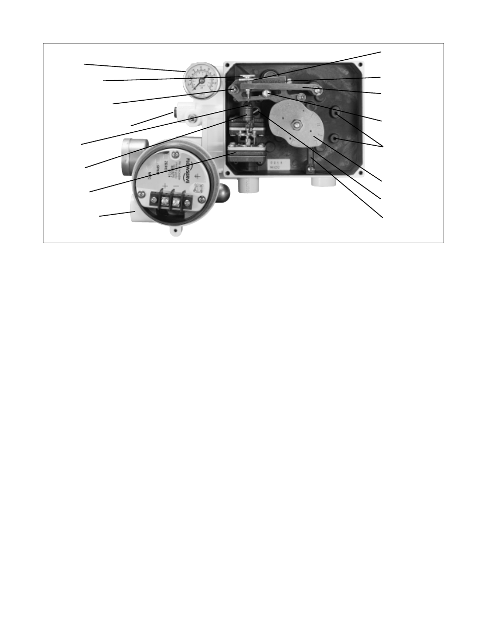
Figure 6: Positioner Adjustments
Output 1
Zero Adjustment
Lock Knob
Cam Follower Arm
(Range Arm)
Output 2 (shown plugged)
Balance
Adjusting Screw
Feedback
Spring
Pilot Relay
Assembly
I/P Transducer
Zero Adjustment
Knob
Span Adjustment
Feedback Spring
Arm
Span Adjustment
Locking Screw
Mounting Holes
for Internal
Electronics
Cam
Orifice Screw
Cam Spring