Flowserve XL90 Series User Manual
Page 4
3. Place cam over the shaft with the appropriate characteristic
facing up and closest to the span arm roller. For Sereg
cams, see Table I. For Accord cams, “D” represents direct-
acting and “R” represents reverse acting.
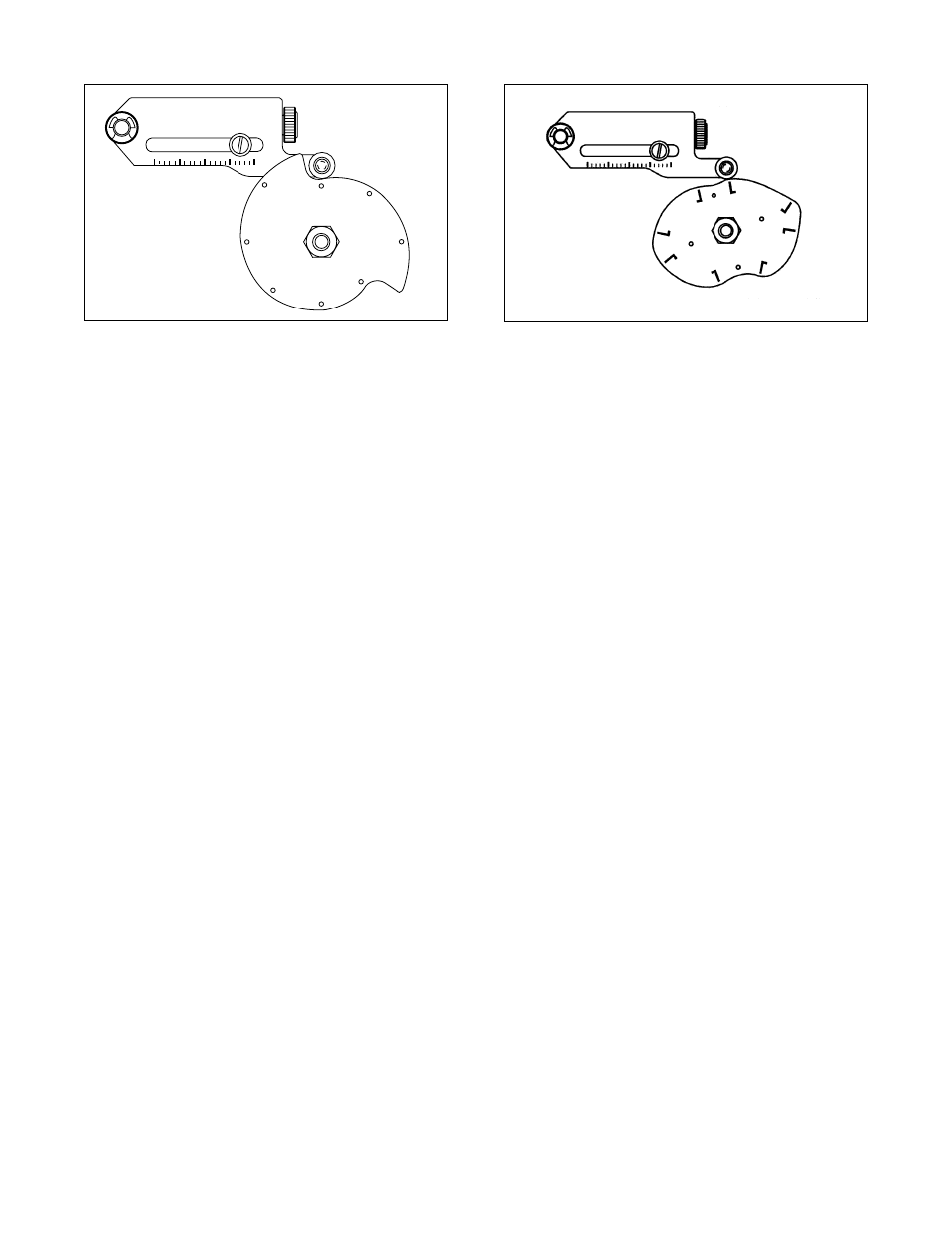
4. A) For NAMUR shaft end connections, make sure the round
mark on the left hand side of the characteristic curve is
lined up with the span arm roller bearing. See Figure 4.
B) For Sereg actuators, make sure the line on the left hand
side of the characteristic curve is lined up through the
middle of the span arm roller bearing. See Figure 5.
5. Tighten jam nut making sure cam does not rotate. Use a flat
screwdriver to prevent cam rotation and shaft flats to pre-
vent shaft rotation (if necessary).
6. Connect supply pressure to port marked ‘Supply.’
7. Stroke actuator/valve two or three times to align position
with actuator. With a 50 percent input signal, tighten all
mounting bolts. Stroke actuator to verify proper alignment.
POSITIONER CALIBRATION
Introduction
Valtek positioners are calibrated at the factory; however, due to
shipping and handling, it may be necessary to check the cali-
bration before operating the valve. The XL90 positioner can be
calibrated to a range of 3-15; two-way split range, 3-9, or 9-15;
and three-way split ranging, 3-7, 7-11, 11-15 psi using the stan-
dard feedback spring.
WARNING: When stroking the actuator during calibration,
keep hands, hair and clothing away from moving parts.
Failure to do so may cause serious personal injury.
Note: Positioners and I/Ps are calibrated at the factory. Use
mechanical adjustments in positioner for calibration. Zero and
span on the I/P should not be used to calibrate the valve.
For calibration, refer to Figure 6 and proceed as follows:
1. For 3-15 or 3-9 psi range, loosen by hand the zero adjust-
ment locking knob and adjust the zero adjustment knob
until the valve begins to stroke with more than 3 psi signal
(for 9-15 psi range adjust to 9 psi).
2. Loosen the span adjustment locking screw no more than
1/8 turn.
3. With a phillips screwdriver adjust the span adjustment so
valve is at full stroke with more than 15 psi for 3-15 or 9-
15 psi range (adjust to 9 psi for 3-9 psi range).
4. Return to 3 psi (or 9 psi for 9-15 psi range) and check the
zero. Repeat steps 1-4 if necessary.
5. Tighten the zero adjustment lock knob and span adjustment
locking screw.
6. Use the same procedure for three-way split range.
7. Connect Cam return spring. See Figure 6.
Positioner Balance Adjustment
CAUTION: Balance pressure is 75 percent of the supply pres-
sure and is the average pressure of output ports 1 and 2.
Balance is preset at factory. However, if this adjustment
becomes necessary, carefully make this adjustment slowly,
allowing the positioner to stabilize. Check after a short while
to make sure balance pressure is correct.
Balance adjustment is set at the factory and should not need
adjustment. Balance adjustment (output pressure level) permits
the equilibrium pressure in both sides of the actuator piston to
be raised or lowered. The average actuator pressure level of out-
put 1 or 2 is approximately 75 percent of supply pressure. For
single-acting actuators, the balance pressure should be left
at the factory setting. If it is necessary to adjust the output pres-
sure level, follow the procedure outlined:
1. If output pressure level is low, before adjusting, check for
leaks in tubing connections between positioner and actua-
tor and check supply pressure.
2. Make certain there is no process force or pressure in the
valve (The valve should be removed or isolated from the
process.)
3. On positioners without gauges, connect gauges to ‘output
1’ and ‘output 2’ lines.
48-4
Flowserve Corporation, Valtek Control Products, Tel. USA 801 489 8611
Figure 5: Alignment for Sereg Cams
Figure 4: Alignment for Accord Cams