General information – Flowserve V-370 R3 Edward Valves User Manual
Page 21
EDWARD UNIVALVE USER INSTRUCTIONS ENGLISH 12-13
21
WARNING
The Edward Univalve
®
is not provided with a pressure
relief device. A pressure relief device must be provided
elsewhere in the piping system to prevent the piping system
pressure from exceeding the maximum rated pressure of
the Univalve.
CONVERTING UNIVALVES
Welded bonnet carbon steel and F22 Univalves, Class 1690
and 2680, can be converted to unwelded types by removing
the seal weld and bonnet, and adding a graphitic gasket and
a locking collar to assure the bonnet will remain locked to
the body. Torque the bonnet per pg. 15.
Unwelded bonnet carbon steel and F22 Univalves, Class
1690 and 2680, can be converted to welded types by adding
a seal weld. Edward Valves does not recommend adding
a seal weld to Univalves with the graphitic bonnet gasket
installed, because of the possibility of over-pressurizing the
threaded region with fluid trapped between the seal weld
and graphitic gasket; remove the gasket before welding.
WELDING UNIVALVES INTO PIPING
WeIding is outside the scope of this manual, but Edward
recommends you consult the appropriate welding
procedure in ASME/ANSI B31, or whatever other codes
apply to your system. When welding Univalves into piping,
make sure there is no foreign material on the seat joint, then
close the valve tightly to approximately 50% of the torque
values in the chart on pg. 19, to avoid distorting the seats.
During subsequent stress relief of the welds, leave the
valve closed to avoid distorting the valve seat. Also, during
stress relief, assure that the valve upperstructure is not
overheated. After welding, open the valve and flush the line
to clean out all foreign matter.
PIPING SUPPORT
Piping should be supported sufficiently to preclude
excessive end loads on the valve.
VALVE INSTALLATION GUIDELINES
Except as noted below, Univalve stop valves and check
valves with springs can be installed in any position.
Installed positions with the valve cover or bonnet below
horizontal, where dirt and scale can accumulate in the valve
neck, should be avoided.
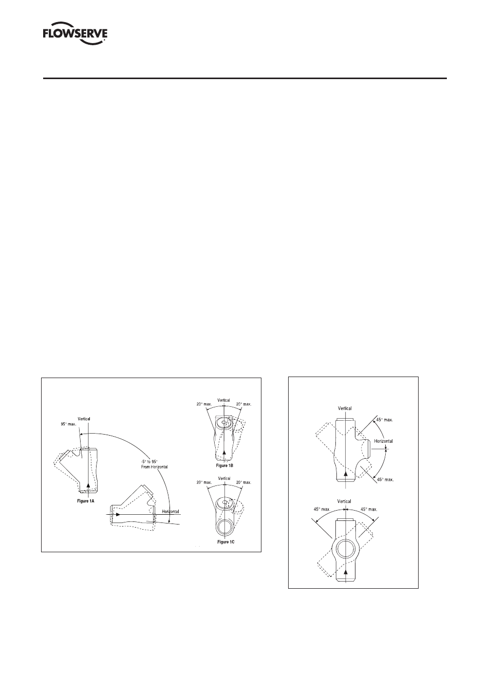
For optimum performance, the orientation limits shown in
Figures 1 and 2 should be observed, even for spring-loaded
check valves.
The orientation limits shown in Figures 1 and 2 must not be
exceeded for Univalve Stop-Check valves and Check valves
without springs. The limitations given for line inclination
and bonnet roll angle should not be combined.
All Check and Stop-Check valves should be installed with
10 or more diameters of straight pipe upstream of the valve
to minimize flow disturbances. For additional information,
refer to the “Technical” section of the Flowserve-Edward
catalog FCD EVENCT0001 or FCD EVENCT0002.
GENERAL INFORMATION
Figure 1
45° Inclined Bonnet Piston-Lift Check Valves
Maximum Check Valve Orientation Limits
Figure 2
Angle Piston-Lift Check Valves
Orientation Limits