3 control station – Flowserve SMB Series Electric Actuators User Manual
Page 31
31
SMB Series/SB Series Installation and Maintenance FCD LMENIM1401-04-AQ – 01/15
flowserve.com
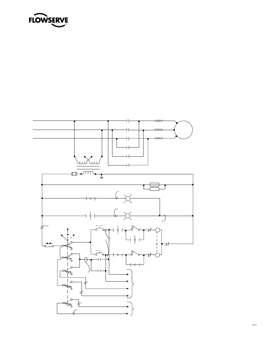
4.7.3 Control Station
The control station consists of
• a five-position Local-Stop-Off-Stop-Remote selector switch, padlockable in each position
• a spring return Open-Close selector switch
• green and red LED lights for position indication.
Typical wiring of the control station in conjunction with the motor control circuit is shown below in
Figure 4.11.
Figure 4.11 – Typical Wiring Diagram – Built-in Reversing Starter and Control Station for a
Three-Phase Power Supply
NOTE: Current design. Earlier control wiring varies slightly.
L1
L2
L3
M1
M2
M3
OL
OL
OL
Motor
T1
T2
T3
CL2
CL2
C
C
C
o
o
o
(H1)(H3) (H2)(H4)
CL1
CL1
CL1
CL1
60
70
7
3
SS
OFF
Black
LOCAL
REMOTE
PB2
STOP
CL1
Red
Green
CL2
CL2
OL
White
Yellow
Blue
PB1
OPEN
CPT
FUSE (X1) (X2)
HTR1
HTR2
4
43
18
45
47
C
o
C
o
5
8
5
Brown
Orange
Pink
REMOTE (31)
REMOTE (30)
Gray
5
5
9
31
30
3
11
3
7
PB3
CLOSE
53
41
5
Purple
STOP (9)
COMMON (11)
CLOSE (51)
OPEN (41)
1
17
55
57
2
To customer’s
equipment
Remote
indication
if required
51