Flowserve SMB Series Electric Actuators User Manual
Page 89
89
SMB Series/SB Series Installation and Maintenance FCD LMENIM1401-04-AQ – 01/15
flowserve.com
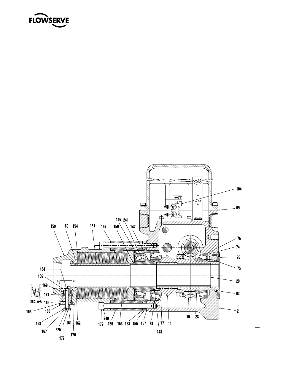
b. If the actuator is mounted on the valve, thread the Stem Nut (piece #20) down the stem until
the splines hit. Put the actuator in manual operation. Rotate the Handwheel in the direction to
move the stem upward—usually the open direction. The Stem Nut will lower as the Handwheel
turns, until it bottoms out on the shoulder in the Drive Sleeve bottom and the stem starts to
move up.
2. Replace the Thrust Sleeve (piece #147) and the Bearing (piece #146). Ensure O-Ring (piece
#148) and Quad Ring (piece #150) are properly installed. Ensure the Thrust Sleeve engages the
splines on the top of the Stem Nut. The Thrust Sleeve will not rotate if engaged improperly.
3. Replace the Thrust Spring Bearing Cartridge (piece #151) along with the Belleville Springs (piece
#153) and Belleville Spring Shim (piece #154). Ensure the Belleville Springs are stacked as
indicated in Figure 8.3. Ensure the O-Ring (piece #162) is installed in the Thrust Sleeve.
4. Install the Spring Housing Adapter (piece #156) using a
1
⁄
32
" gasket.
5. Ensure the Seal Bushing (piece #160) and the O-Ring (piece #161) are properly installed in the
Spring Housing (piece #159).
6. Install the Spring Housing (piece #159) using a
1
⁄
32
" gasket.
Figure 8.3 – SB-1 Parts Diagram
01-416-0028-4