Flowserve 520si Digital Positioner User Manual
Page 14
14
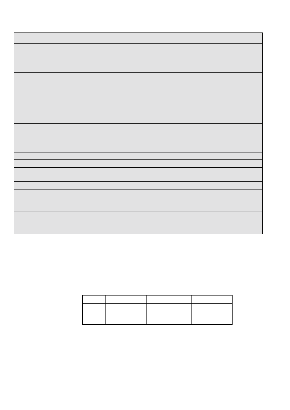
Logix 520 si Status Condition Codes
Colors Identifier
Indication and resolution
R - - -
Any sequence starting with a red light indicates that there is an operational problem with the unit.
RGRR
26
Position Deviation - The position has exceeded user defined error band between command and
position.
RYYY
27
Hall sensor non-motion - Check to make sure the air supply is connected. This error may be cleared
by briefly pushing the Quick-Cal button, which will force the positioner to use the parameters from the
last good calibration. If the positioner still does not operate replace the pneumatic relay assembly.
RYYR
28
Hall sensor lower position - Check to make sure the air supply is connected. This error may be
cleared by briefly pushing the Quick-Cal button, which will force the positioner to use the parameters
from the last good calibration. If the positioner still does not operate replace the pneumatic relay
assembly.
RYRY
29
Hall sensor upper position - Check to make sure the air supply is connected. This error may be
cleared by briefly pushing the Quick-Cal button, which will force the positioner to use the parameters
from the last good calibration. If the positioner still does not operate replace the pneumatic relay
assembly.
RRGG
30
1,23 V reference - Bad electronic assembly, replace.
RRGR
31
12-bit A/D reference - Bad electronic assembly, replace.
RRYG
32
Temperature limit - The internal positioner temperature is currently exceeding operational limits of
-40 ˚C (-40 ˚F) or 85 ˚C (185 ˚F).
RRYY
33
Piezo voltage - Bad electronic assembly, replace.
RRYR
34
Board current high - Check internal wiring and connectors for electrical shorts, if no shorts bad
electronic assembly, replace.
RRRG
35
12-bit D/A reference - Bad electronic assembly, replace.
RRRY
36
EEprom checksum error - The checksum of the internal data has become corrupted. Cycle power and
complete a Quick-Cal if needed. Check internal data to verify correct settings. If the error still occurs,
bad electronic assembly, replace.
13
Version number checking- The version number of the embedded code may be checked at any time except during a
calibration by holding down the ∆ button. This will not alter the operation of the unit other than to change the blink
sequence to 3 blinks indicating the major version number. Holding the ∇ button will give the minor version number
without affecting operation. The version codes are interpreted by adding up the numbers assigned according to the
following table:
Color
First blink value
Second blink value Third blink value
Green
0
0
0
Yellow
9
3
1
Red
18
6
2
For example if holding the ∆ button gave a G-G-R code, and holding the ∇ button gave a Y-Y-G code then the resulting version number
would be (0+0+2).(9+3+0) or version 2.12.