6 tubing positioner to actuator – Flowserve 520si Digital Positioner User Manual
Page 6
6
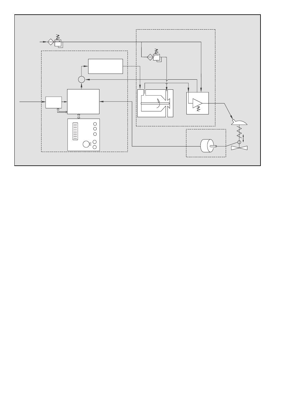
Figure 1: Logix 520
si
Principle of Operation
5 PRINCIPLE OF OPERATION
The Logix 520 si positioner is a digital positioner that incor-
porates HART protocol for communication. The positioner
consists of three main modules:
1. The microprocessor-based electronic control
module includes HART communications and direct local
user interface switches
2. The piezo valve-based electro-pneumatic converter
module
3. The infinite resolution valve position sensor.
The basic positioner operation is best understood by refer-
ring to Figure 1. The complete control circuit is powered by
the two-wire, 4-20 mA command signal. The HART module
sends and receives the superimposed FSK HART digital com-
munications over the 4-20 mA signal wires providing two-
way remote digital communications to the microprocessor.
The analog 4-20 mA command is passed to the microproc-
essor, where it is compared to the measured valve stem
position. The control algorithm in the processor performs
control calculations and produces an output command to
the piezo valve, which drives the pneumatic amplifier. The
position of the pilot valve in the pneumatic amplifier is meas-
ured and relayed to the inner loop control circuit. This two-
stage control provides for more responsive and tighter con-
trol than is possible with a single stage control algorithm.
The pneumatic amplifier controls the airflow to the actuator.
The change of pressure and volume of the air in the actuator
causes the valve to stroke. As the valve approaches the de-
sired position, the difference between the commanded po-
sition and the measured position becomes smaller and the
output to the piezo is decreased. This, in turn, causes the
pilot valve to close and the resulting flow to decrease, which
slows the actuator movement as it approaches, the new com-
manded position. When the valve actuator is at the desired
position, the pneumatic amplifier output is held at zero, which
holds the valve in a constant position.
6 TUBING POSITIONER TO ACTUATOR
After mounting has been completed, tube the positioner to
the actuator using the appropriate compression fitting con-
nectors:
Air connections: 1/4” NPT (standard air connection)
Auxiliary power: Pressurized air or permissible gases, free
of moisture and dust in according with IEC 770 or ISA
7.0.01.
Pressure range: 1,5 – 6,0 bar (22 – 87 psi)
For connecting the air piping, the following notes should be
observed:
1. The positioner passageways are equipped with filters,
which remove medium and coarse size dirt from the
pressurized air. If necessary, they are easily accessible for
cleaning.
2. Supply air should meet IEC 770 or ISA 7.0.01 require-
ments. A coalescing filter should be installed in front of
the supply air connection Z. Now connect the air supply
to the filter, which is connected to the Logix 500 si series
positioner.
3. With a maximum supply pressure of 6 bar (87 psi) a
regulator is not required.
4. With an operating pressure of more than 6 bar (87 psi), a
reducing regulator is required. The flow capacity of the
regulator must be larger than the air consumption of the
positioner (7 Nm
3
/hr @ 6 bar / 4,12 scfm @ 87 psi).
5. Connect the outlet connector Y of the positioner to the
actuator with tubing, independent of the action (direct or
reverse).
Local
User
Interface
4 – 20 mA
+ HART
HART
Inner Loop
Piezo Control
Stroke
Inner Loop
Position Feedback
1 Digital Control Circuit
2 Electro-pneumatic
Converter Module
3 Valve
Position
Sensor
Filter / Regulator
for Supply Air
22 – 87 psi (1.5 – 6.0 bar)
Supply Air
∑
-
Micro
Processor
Gain
Pressure Regulator
Piezo Valve
Pneumatic
Amplifier
Control
Valve
+