Checking or setting internal regulator pressure, Figure 18: stem position sensor adjustment – Flowserve Logix 1200e LGAIM0044 User Manual
Page 18
44-18
Flowserve Corporation, Valtek Control Products, Tel. USA 801 489 8611
stroke calibration. Release the Quick-Cal button once
calibration has started. The positioner will automati-
cally stroke the valve. The stroke sequence will be to
the extremes (open to close), to the mid stroke, then
to the signal position. No LED will blink during this
process.
NOTE: If Quick-Cal is interrupted during calibration
the mode of the positioner may stay in digital, requiring
HART communications to place it back into analog.
If calibration was successful, upon completion the
green LED will blink and the valve will be in control
mode. If the yellow LED blinks immediately after a
stroke calibration, this usually indicates that the valve
did not stroke. Check the air supply and cable connec-
tions. If a calibration error occurred, the red LED will
blink. The cause of a red LED is generally a stem posi-
tion linkage/feedback sensor alignment problem. For
linear linkage, the active electrical feedback angle is
65 degrees. For rotary linkage, the active electrical
feedback angle is 95 degrees. The red LED indicates
that the mechanical travel is not centered within the
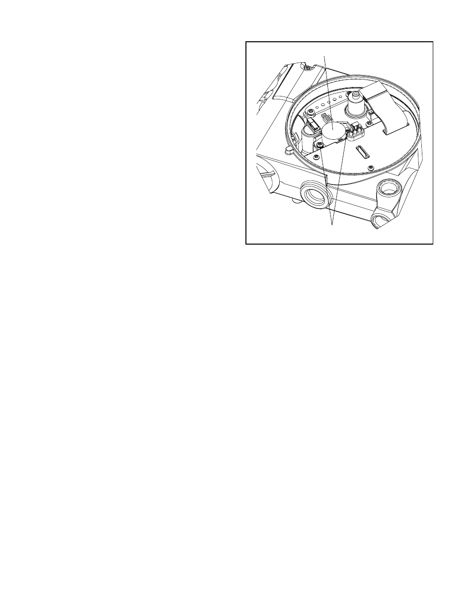
electrical sensor travel. If a red LED is blinking after a
stroke calibration, loosen the feedback sensor mount-
ing screws as shown in Figure 18. Turn the stem posi-
tion sensor slowly while watching the LED indicators.
Try small movements, both clockwise and counter-
clockwise. If the yellow LED begins to blink, the feed-
back sensor has been correctly moved into range.
Tighten the feedback sensor mounting screws and
repeat the Quick-Cal procedure. If the LED remains
red even after moving the full length of the sensor slot,
verify the following items are correctly set:
LIN_VALV/ROT_VALV DIP switch setting, stem clamp
and take-off arm height.
NOTE: If the stroke calibration stops in the closed
position, the error occurred when the position
sensor/linkage was at closed position. If the stroke
calibration stops in the open position, the error
occurred when position sensor/linkage was at the
open position. No calibration parameters are saved if
an error occurs. If the power to the positioner is
removed, the unit will power-up with the previous
configuration parameters. A successful calibration will
save parameters.
If the valve does not stroke after pressing the Quick-
Cal button, this may be an indication that the internal
regulator pressure and/or the driver module minimum
pressure is low. Refer to the following instructions to
check and set the internal regulator and minimum
pressure settings.
NOTE: Ensure that all linkages are tight and correctly
mounted before attempting to calibrate. Loose or
incorrectly mounted linkage will cause calibration fail-
ure and difficulty in troubleshooting.
Checking or Setting Internal Regulator Pressure
The tools and equipment used in the next procedure
are from indicated vendors.
1. Make sure valve is bypassed or in a safe condition.
2. Disconnect the air supply from the positioner.
3. Remove the main cover and the
1
/
16
inch flexible
tubing from the driver module orifice.
4. Obtain a barbed tee (Pneumadyne part No. SBF-
16T or equivalent) and two pieces of
1
/
16
inch flexi-
ble tubing, a few inches in length each.
5. Connect the
1
/
16
inch flexible tubing, found in the
positioner, to the barbed tee. Using one of the new
flexible tubing pieces connect the barbed tee to the
orifice. Connect the remaining tee port to a 0 to 30
psi pressure gauge.
6. Reconnect the air supply to the positioner and read
the internal regulator pressure on the 0 to 30
gauge. The internal pressure should be set to 21.5
±0.5 psi. If adjustment in needed, scrape off the sil-
icon compound covering the screw. Then adjust the
regulator pressure by turning the setscrew on top
of the regulator with a small screwdriver.
7. Once the regulator pressure is set, remove the air
supply to the positioner, remove the barbed tee,
and reconnect the positioner's flexible tubing to the
orifice.
8. Reconnect air supply to positioner.
Figure 18: Stem Position Sensor
Adjustment
Rotate Stem Position Sensor slol
Stem Position
Sensor Mounting Screws (2)