Troubleshooting, Introduction, Theory of operation – Flowserve Logix 1200e LGAIM0044 User Manual
Page 30
44-30
Flowserve Corporation, Valtek Control Products, Tel. USA 801 489 8611
Troubleshooting
Introduction
This guide is designed to assist the user in trouble-
shooting the Logix™ 1200 digital positioner. The Logix
1200 positioner is a two-wire, HART communication-
based device, and is used in conjunction with Val-
Talk™ and SoftTools™ software or the HART 275
handheld communicator. As part of this troubleshoot-
ing guide, a number of recommendations are pro-
vided, which should improve operation and allow for
accurate configuration.
Theory of Operation
NOTE: Variable names found in Figure 18 are used in
ValTalk software and can be found in the Measured
Values Status screen.
The Logix 1200 digital positioner receives power from
the two-wire, 4-20 mA input signal. However, since this
positioner utilizes HART communications, two sources
can be used for the command signal: analog or digital.
With the analog source, the 4-20 mA signal is used for
the command source. With the digital source, the level
of the input 4-20 mA signal is ignored and a digital sig-
nal (sent via HART) is used as the command source.
The command source can be accessed with ValTalk or
SoftTools software, or the HART 275 communicator.
Whether in analog or a digital source, 0 percent is
always defined as the valve’s closed position and 100
percent is always defined as the valve’s open position.
With the analog source, the 4-20 mA signal is con-
verted to a percentage. During loop calibration, the
signals corresponding to 0 percent and 100 percent
are defined.
At this point, the command value is passed through a
characterization/limits modifier block. The positioner
no longer uses cams or other mechanical means to
characterize the output of the positioner. This function
is performed by the software, which allows for user
adjustment in the field.
The positioner has two basic modes: Linear and Cus-
tom characterization. In the Linear mode, the com-
mand signal is passed straight through to the control
algorithm in a 1:1 transfer. If Custom characterization
is enabled, the command source is mapped to a new
output curve through a 21-point, user-defined curve. In
addition, two user-defined features, Soft Limits and
MPC (Minimum Position Cutoff), may affect the final
command signal. The actual command being used to
position the stem is called Control Command. The
Control Command is the actual positioning command
after any characterization or user limits have been
evaluated.
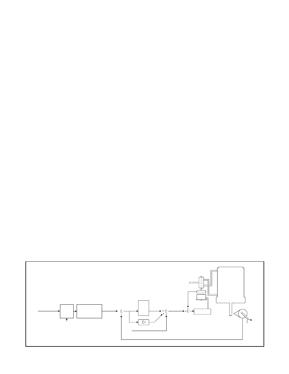
The Logix 1200 positioner uses a two-stage, stem-
positioning algorithm. The two stages are comprised
of an inner-loop, spool control and an outer-loop stem
position control. Referring to Figure 18, the stem posi-
tion sensor provides a measurement of the stem
movement. The Control Command is compared
against the Stem Position. If any deviation exists, the
control algorithm sends a signal to the inner-loop con-
trol to move the spool up or down, depending on the
deviation. The inner-loop then quickly adjusts the
Stem
Position
Sensor
Tubed ATO
Sensor
Air Supply
Modulator
Coil Current
Inner Loop
Spool Control
Inner-Loop
Hall Sensor
O
utput
Control
Algorithm
Deviation
Position
P
max
P
min
G
mult
Integration Summer
Inner Loop O
ffset
Analog
Digital
Command
Source
Command in
(Digital mode)
+
Control
Command
4–
20
(Analog Mode)
Linear Mode
Characterization
Soft Limits
MPC
D/A O
utput
Percentage