Flowserve 505si Series Digital Positioner User Manual
Page 5
5
®
User Instructions Logix 505si - LGENIM0505-00 03/09
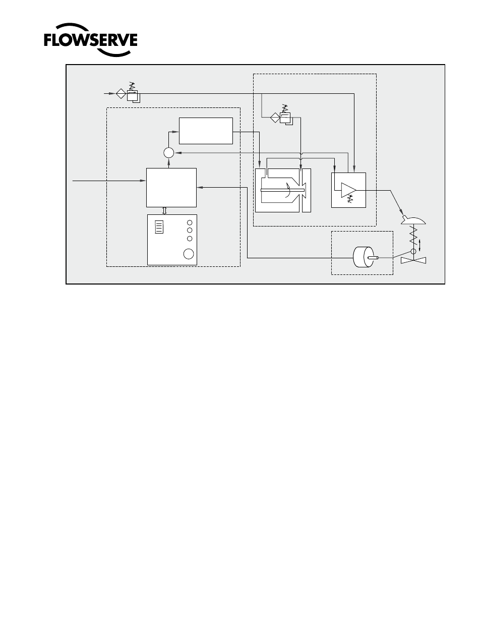
Figure 1: Logix 505si Principle of Operation
5
PRinCiPLE OF OPERATiOn
The Logix 505si positioner is a basic digital positioner
consisting of three main modules:
1. The microprocessor based electronic control
module includes direct local user interface switches
2. The piezo valve based electro-pneumatic converter
module
3. The infinite resolution valve position sensor.
The basic positioner operation is best understood by
referring to Figure 1. The complete control circuit is
powered by the two-wire, 4-20 mA command signal. The
analog 4-20 mA command is passed to the microproces-
sor, where it is compared to the measured valve stem po-
sition. The control algorithm in the processor performs
control calculations and produces an output command
to the piezo valve, which drives the pneumatic amplifier.
The position of the pilot valve in the pneumatic amplifier
is measured and relayed to the inner loop control circuit.
This two-stage control provides for more responsive
and tighter control than is possible with a single stage
control algorithm. The pneumatic amplifier controls
the airflow to the actuator. The change of pressure and
volume of the air in the actuator causes the valve to
stroke. As the valve approaches the desired position,
the difference between the commanded position and
the measured position becomes smaller and the output
to the piezo is decreased. This, in turn, causes the pilot
valve to close and the resulting flow to decrease, which
slows the actuator movement as it approaches the new
commanded position. When the valve actuator is at the
desired position, the pneumatic amplifier output is held
at zero, which holds the valve in a constant position.
6
TUbing POSiTiOnER TO ACTUATOR
After mounting has been completed, tube the positioner
to the actuator using the appropriate compression fit-
ting connectors:
Air connections: 1/4” NPT (standard air connection)
Auxiliary power: Pressurized air or permissible gases,
free of moisture and dust in according with IEC 770 or
ISA 7.0.01.
Pressure range: 1,5 – 6,0 bar (22 – 87 psi)
For connecting the air piping, the following notes should
be observed:
1. The positioner passageways are equipped with
screws, which remove medium and coarse size dirt
from the pressurized air. If necessary, they are easily
accessible for cleaning.
2. Supply air should meet IEC 770 or ISA 7.0.01
requirements. A coalescing filter should be installed in
front of the supply air connection Z. Now connect the
air supply to the filter, which is connected to the Logix
500 Series positioner.
3. With a maximum supply pressure of 6 bar (87 psi)
a regulator is not required.
4. With an operating pressure of more than
6 bar (87 psi), a reducing regulator is required. The
Local
User
Interface
4 – 20 mA
Stroke
Inner Loop
Position Feedback
1 Digital Control Circuit
2 Electro-pneumatic
Converter Module
3 Valve Position
Sensor
Inner Loop
Piezo Control
Filter / Regulator
for Supply Air
1.5 – 6.0 bar (22 – 87 psi)
Air Supply
-
Micro-
Processor
Pressure Regulator
Piezo Valve
Pneumatic
Amplifier
Control Valve
+
Input