Flowserve 505si Series Digital Positioner User Manual
Page 8
8
®
User Instructions Logix 505si - LGENIM0505-00 03/09
b.
Split range - Split range selection is used to limit the
action control region to either 4 - 12 mA or 12 - 20 mA.
Thisallows two valves to be controled from the same
4 - 20 mA control line.
•
Full: The 505si uses the full 4 - 20 mA range to control
the valve.
•
Split: The 505si uses either 4 - 12 or 12 - 20 mA to
control the valve.
c.
4 - 12 (12 - 4) or 12 - 20 (20 - 12) is used to select the
range used for control. This switch is only active when
the full/split switch is in the split position.
•
4 - 12 (12 - 4) Full valve travel in the 4 - 12 mA range
for ATO (12 - 4 mA range for ATC)
•
12 - 20 (20 - 12) Full valve travel in the 12 - 20 mA
range for ATO (20 - 12 mA range for ATC)
d.
gain Switch – This switch adjusts the position control
algorithm of the positioner for standard or low gain.
•
Standard: Placing the switch to the left opmizes
the response for low friction, high performance control
valves. This setting provides for optimum response
times when used with most low friction control valves.
•
Low: Placing the switch to the right reduces the gain. It
also optimizes the response for valves and actuators with
high friction levels. This setting slightly slows the
response and will normally stop limit cycling that can
occur on high friction valves.
WARning: During the Quick-Cal operation the valve
may stroke unexpectedly. Notify proper personnel
that the valve will stroke, and make sure the valve is
properly isolated.
8.3
QUiCK-CAL Operation
The QUICK-CAL button is used to locally initiate a
calibration of the positioner. Pressing and holding the
QUICK-CAL button for approximately 3 seconds will ini-
tiate the calibration. The settings of all the configuration
switches are read and the operation of the positioner
adjusted accordingly. A QUICK-CAL can be aborted at
any time by briefly pressing the QUICK-CAL button and
the previous settings will be retained. While the calibra-
tion is in progress you will notice a series of different
lights flashing indicating the calibration progress. When
the lights return to a sequence that starts with a green
light the calibration is complete. (see the section 9 for
an explanation of the various light sequences)
8.4
Factory reset
Hold Quick cal button while applying power and all of
the internal variables including calibration will be reset
to factory defaults. The positioner must be re-calibrated
after a factory reset.
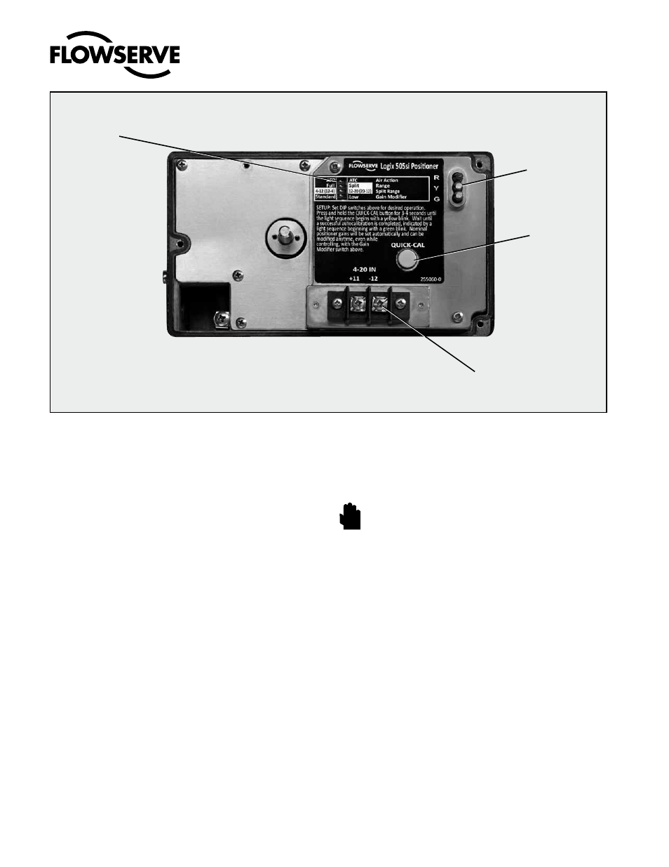
Figure 4: Logix 505si Local interface
Configuration
Switches
4-20 mA Input
LED Status
Lights
Quick-Cal
Switch
STOP!