Flowserve 505si Series Digital Positioner User Manual
Page 6
6
®
User Instructions Logix 505si - LGENIM0505-00 03/09
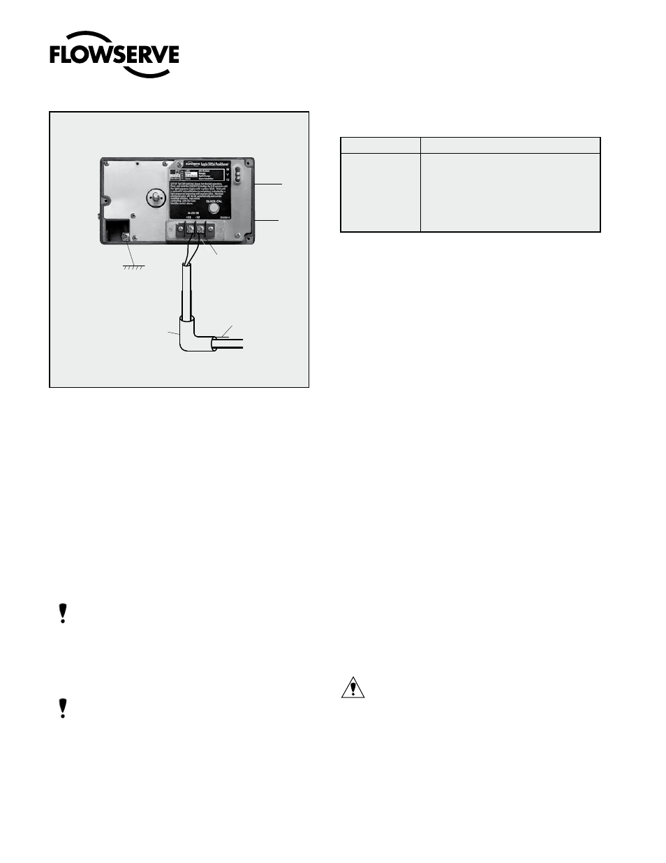
grounding Screw
The grounding screw, located inside the positioner
cover, should be used to provide the unit with an ad-
equate and reliable earth ground reference. This ground
should be tied to the same ground as the electrical con-
duit. Additionally, the electrical conduit should be earth
grounded at both ends of its run. The grounded screw
must not be used to terminate signal shield wires.
Compliance Voltage (Figure 3)
Output compliance voltage refers to the voltage limit
the current source can provide. A current loop system
consists of the current source, wiring resistance, barrier
resistance (if present), and the Logix 505si impedance.
The Logix 505si requires that the current loop system
allow for a 6,0 VDC drop across the positioner at maxi-
mum loop current.
CAUTiOn: Never connect a voltage source directly
across the positioner terminals. This could cause per-
manent circuit board damage.
flow capacity of the regulator must be larger than the
flow capacity of the positioner (7 Nm
3
/h @ 6 bar / 4,12
scfm @ 87 psi).
5. Connect the outlet connector Y of the positioner
to the actuator with tubing, independent of the action
(direct or reverse).
7
WiRing AnD gROUnDing gUiDELinES
Electrical connections: signal cable with cable passage
(NPT or M20 x 1,5) to terminals 2 x 2,5 mm
input signal: 4 – 20 mA
nOTE: Observe the minimum requirements of voltage
and equivalent electrical load: 6,0 VDC / 300
Ω / at
20 mA
The performance is ensured only for a minimum input
current of 3,6 mA.
For wiring, the following notes should be observed:
nOTE: The input loop current signal to the Logix 505si
should be in shielded cable. Shields must be tied to a
ground at only one end of the cable to provide a place
for environmental electrical noise to be removed from
the cable. In general, shield wire should be connected
at the source. (Figure 2)
Connect the 4-20 mA current source to terminals +11
and -12 (Figure 2).
Figure 2: Wiring Diagram
Table 10: Connection Table
Connection
Description
+11
Input+ 4..20 mA
-12
Input- 4..20 mA
Y (0
⇒)
Pneumatic output signal (outlet)
Z (0
⇐)
Air supply
Internal Housing
EARTH Terminal
4-20 mA Signal
Connect Shield at Source Ground
-
+
4-20 mA Current Source
Shielded Cable
Y
Z