Flowserve 505si Series Digital Positioner User Manual
Page 9
9
®
User Instructions Logix 505si - LGENIM0505-00 03/09
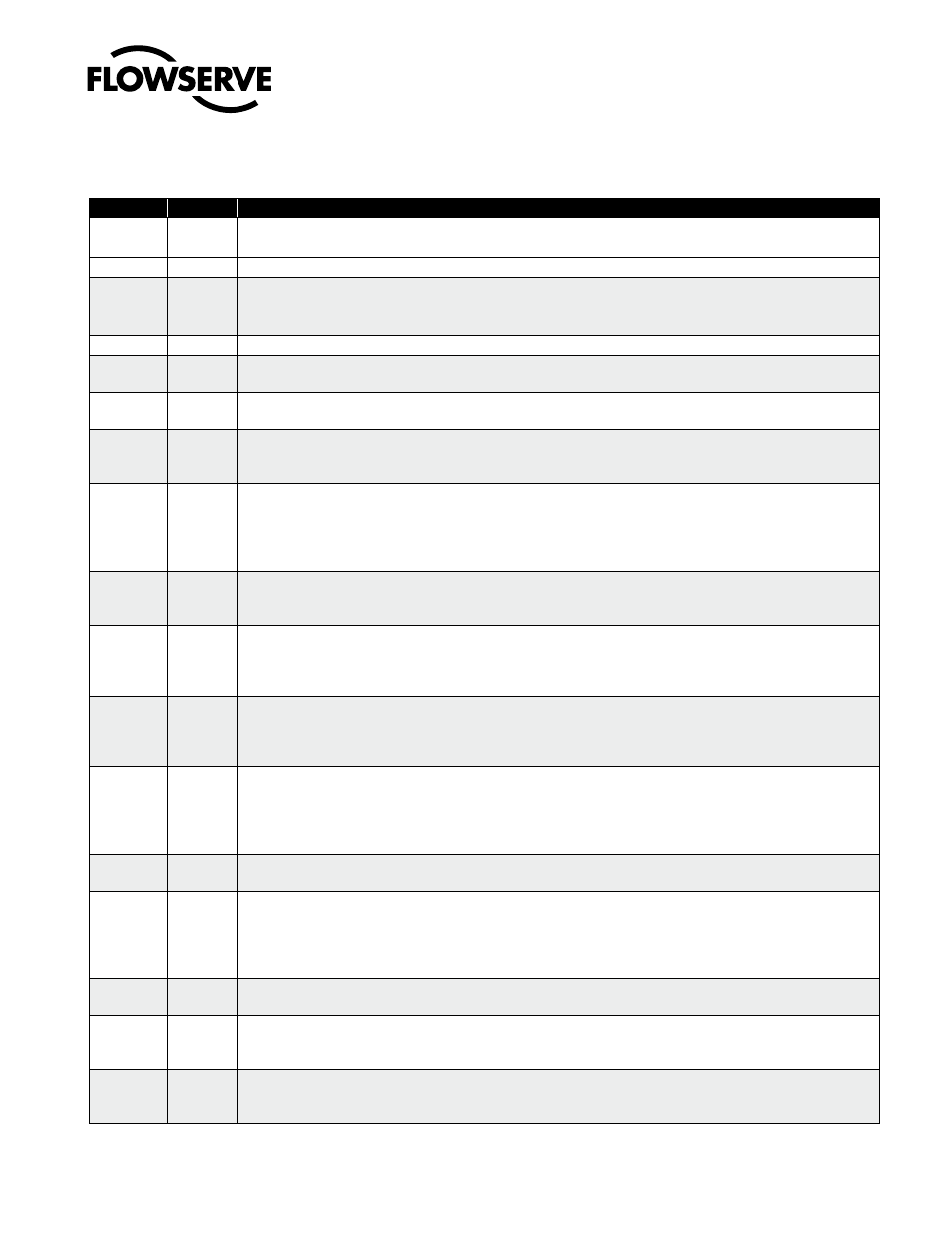
Logix 505si Status Condition Codes
9 STATUS CODES
Colors
identifier
indication and resolution
g - - -
Any sequence starting with a Green light flashing first is a normal operating mode and indicates that there are no
internal problems.
GGGG
1
no errors, alerts, or warnings.
GGGY
2
MPC active - The command is below the 1% command limit for tight shutoff feature. This is a normal
condition for a closed valve. To clear the condition, adjust the command signal above the specified MPC value, or
disable the feature by moving the Tight Shutoff switch to the off position and recalibrating.
GGYR
3
LED test mode, initializing - This sequence should only be visible for 3 sequences when powering up the unit.
Y - - -
Any sequence starting with a yellow light indicates that the unit is in a special calibration or test mode, or that there
was a calibration problem.
YYYY
4
Relay not operating during calibration – Most Likely the Air supply is not connected. Could also be due to a bad
pneumatic relay, failed electronics, or a loose or bad connector from the electronics to the relay.
YYYR
5
Command minimum saturated - Calibration error indicating that the 4-20 mA signal corresponding to the minimum
command was too low. Adjust the signal to higher range and re-do the calibration. This error may be cleared by briefly
pushing the quick-cal button, which will force the positioner to use the parameters from the last good calibration.
YYRR
6
Command span - Calibration error indicating that the 4-20 mA signal was below the minimum calibration span.
The minimum calibration span is 3.0 mA. This error may be cleared by briefly pushing the quick-cal button, which
will force the positioner to use the parameters from the last good calibration or if the and buttons are pressed
simultaneously the calibrated span will be used even though it is less than the recommended range. may be cleared by briefly
pushing the quick-cal button, which will force the positioner to use the parameters from the last good calibration.
YYRY
7
Command maximum saturated - Calibration error indicating that the 4-20 mA signal corresponding the maximum
command was too high. Adjust the signal a lower range and re-do the calibration. This error may be cleared by briefly pushing the
quick-cal button, which will force the positioner to use the parameters from the last good calibration.
YRRR
9
Feedback span - The range of motion of the position feedback arm was too small. Check for loose linkages and/or adjust
the feedback pin to a position closer to the follower arm pivot to create a larger angle of rotation. Also check the air supply
to make sure the system is properly connected. This error may be cleared by briefly pushing the quick-cal button, which
will force the positioner to use the parameters from the last good calibration.
YRRY
10
Feedback 100 saturated - Calibration error indicating that the position sensor was out of range during the calibration. To
correct the condition, adjust the positioner mounting, linkage or feedback potentiometer to move the position sensor back
into range then restart the calibration. This error may be cleared by briefly pushing the quick-cal button, which will force the
positioner to use the parameters from the last good calibration.
YRYY
12
Feedback no-motion during calibration - Indicates that there was no motion of the actuator based on the current
stroke time configuration. Check linkages and air supply to make sure the system is properly connected. If the time
out occurred because the actuator is very large then simply retry the Quick cal and the positioner will automatically
adjust for a larger actuator by doubling the time allowed for movement. This error may be cleared by briefly pushing
the quick-cal button, which will force the positioner to use the parameters from the last good calibration.
YRYG
13
Setting iL offset (during Stroke calibration) - An automatic step in the calibration process that is done with the valve
a 50% position. This must be completed for proper operation.
YRYR
14
Feedback 0 saturated - Calibration error indicating that the position sensor was out of range during the valve a 50%
position. This must be completed for proper operation. calibration. To correct the condition, adjust the positioner
mounting, linkage or feedback potentiometer to move the position sensor back into range then restart the calibration.
This error may be cleared by briefly pushing the quick-cal button, which will force the positioner to use the parameters
from the last good calibration.
15
Stroke Calibration in Progress - Calibration sequence started using the local quick-cal button. It may be cancelled
by briefly pushing the quick-cal button.
YRGY
16
Unable to set iL offset during QUiCK-CAL – This may occur on very large or small actuators on the first calibration
attempt. The Logix 505 will automatically adjust parameters for future calibrations. To Continue briefly push the
quick-cal button to acknowledge and restart quick-cal.
YRGR
17
Feedback unstable during calibration - Check for loose linkages or loose positioner sensor. This error may be
cleared by briefly pushing the quick-cal button, which will force the positioner to use the parameters from the last
good calibration.