3 travel stop bolts and accessories, 4 grounding system – Flowserve LHS Hydraulic Heavy-Duty Actuator Series User Manual
Page 10
10
LHS Hydraulic Heavy-Duty Actuator Series FCD LFENIM0003-00-AQ 7/14
a
WARNING: The lifting lugs are appropriate for actuator lifting alone and not for the valve and actuator assembly
lifting. Avoid that during the handling, the actuator passes above the staff. The actuator should be handled with
appropriate lifting means. The weight of the actuator is reported on the packing slip and on overall-dimensions
drawings furnished with the documents accompanying the actuator.
2.3 Travel Stop Bolts and Accessories
All actuated valves require accurate travel-stop adjustments at both ends of the stroke to obtain optimum performance
and valve seat life. Adjust the travel-stop bolts of the actuator for the proper open and close valve positions, per valve
manufacturer’s recommendations.
The LHS actuators have travel-stop adjustments in both the clockwise and counter-clockwise directions.
The +/- 5-degree adjustment feature provides shaft rotation from 80 to 100 degrees overall.
The adjustment of the travel-stops is performed in accordance with the following steps. Refer to Figures 19, 20, 21 and 22.
Hydraulic cylinder stop (25): Loosen the seal nut (if present) with a proper wrench. Screw or unscrew the stop (25),
using a proper Allen key, while keeping the seal nut stationary. Tighten the seal nut.
Spring container stop (7): Remove the spring container end flange (11) after unscrewing the hex screws (10). Screw or
unscrew the end stop (7) to the desired position, using a proper Allen key. Replace the end flange and tighten the hex screws.
Hydraulically stroke the actuator several times to assure proper operation. The stem adaptor should not bind during
operation. If the actuator is equipped with a switch, positioner or other accessories, adjust them at this time.
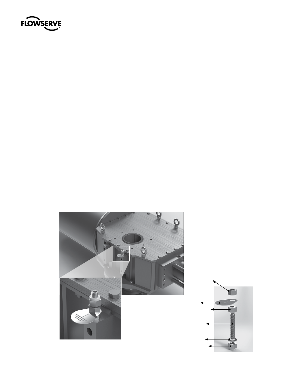
2.4 Grounding System
For the actuator earthing, use the grounding kit, shown in Figure 9:
Figure 9: Grounding Kit Assembled
Figure 11: Grounding Kit
Figure 10: Grounding Kit – Exploded View
High Nut ISO 4033-M8
Ground Nameplate
High Locking Nut with Nylon Insert-ISO 7040-M8
Lock Washer, DIN 6798 A, Ø8
Grub Screw-ISO 4026-M8x45
High Nut ISO 4033-M8