3 hydraulic cylinder maintenance – Flowserve LHS Hydraulic Heavy-Duty Actuator Series User Manual
Page 18
18
LHS Hydraulic Heavy-Duty Actuator Series FCD LFENIM0003-00-AQ 7/14
4.2.4 Before reassembling the new spring module to body, make sure stud threads are free of any dirt, shavings, or
other debris. Clean threads with rag and solvent if required, and lubricate threads with an anti-seize compound.
Assemble the new spring can, following the reverse procedure as described in points 4.2.4 to 4.2.3.
Readjust the travel-stop (25) of the hydraulic cylinder, as instructed in paragraph 2.3.
4.3 Hydraulic Cylinder Maintenance
The hydraulic cylinder maintenance mainly consists in the replacement of all parts that may degrade in the course of
time, even in the absence of faults. These components are the O-rings and the sliding elements of the piston.
The substitution of cylinder components (or of the whole cylinder) is not expected over the entire actuator life.
However, accidental events may result in damage to these components. In these cases, proceed as described in the
following steps.
There are two possible types of maintenance: standard maintenance which can be performed in the field without the
need to remove the hydraulic cylinder from the actuator, and a more thorough one, following unexpected events,
which often can be performed only after removing the cylinder from the actuator.
Standard in–field Maintenance – perform the following steps:
The reference drawing is Figure 20.
a
WARNING: ensure that the hydraulic connection ports of the cylinder are disconnected. Also make sure that
all hydraulic supplies to the control unit and all power supplies are disconnected. Finally, make sure that the
actuator is in fail position, i.e. that it is not locked in a position with the spring compressed by means of locking
device.
4.3.1 If necessary, feed the hydraulic cylinder from the port on the head flange (19) at minimum necessary
pressure to facilitate the movement of the scotch yoke and assure the total retraction of the piston rod (20).
In this way the spring is fully extended. Unscrew and remove the travel stop of the hydraulic cylinder. For
removing the stop, refer to the indications given in paragraph 2.3.
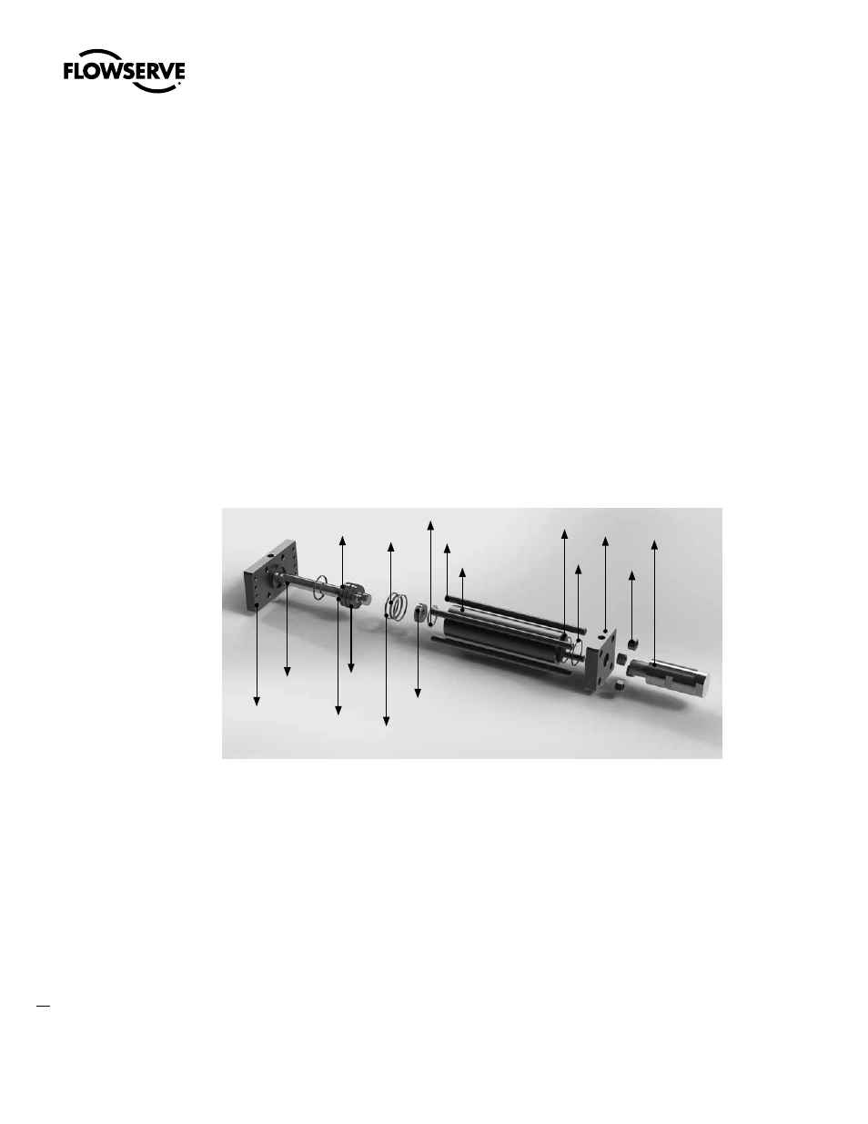
Figure 20: Exploded View of Hydraulic Cylinder
19
34
33
32
31
30
29
28
27
26
25
24
23
22
21
20