4 scotch yoke housing maintenance – Flowserve LHS Hydraulic Heavy-Duty Actuator Series User Manual
Page 19
19
flowserve.com
LHS Hydraulic Heavy-Duty Actuator Series FCD LFENIM0003-00-AQ 7/14
4.3.2 Remove at least two of the tie rods (31) positioned on the upper part of the cylinder by unscrewing the nuts
on the sides of the end flange and of the head flange (or unscrewing the tie rods from the head flange if
threaded into the flange). This operation provides two free holes to be used for lifting the end flange (27).
Screw two male eyebolts in these two holes and connect the end flange to a lifting system. Care should be
taken to choose a lifting system suitable for the weight of the cylinder. Refer to the weight table shown in
Figures 24 and 25. Remove all other tie rods (31), following the same procedure described in point 4.3.2.
Then remove carefully the end flange (27) from the tube (30).
4.3.3 Finally, remove the tube (30). Take care not to scratch or dent the honed and plated inner surface of the tube.
Remove the O-rings (28) from the flange; remove the O-ring of the piston (33) and finally the guide rings
(23) from the piston. Clean all surfaces of piston and flanges in contact with these components with rag
and solvent. Brush the O-ring grooves with a light oil film and install the new O-rings. Spread a thin layer
of grease on the bottom of the guide ring grooves and install the new guide rings (23). Clean the internal
surface of the tube (30) and lubricate with a protective oil film.
4.3.4 Reassemble the parts of the cylinder with the reverse procedure as described in points 4.3.3 to 4.3.2. The
tie rods should be tightened using a torque wrench, alternating between opposite holes, applying a torque
according to according to specific tables, available upon request to Flowserve After Sales Department.
Readjust the stops as instructed in paragraph 2.3.
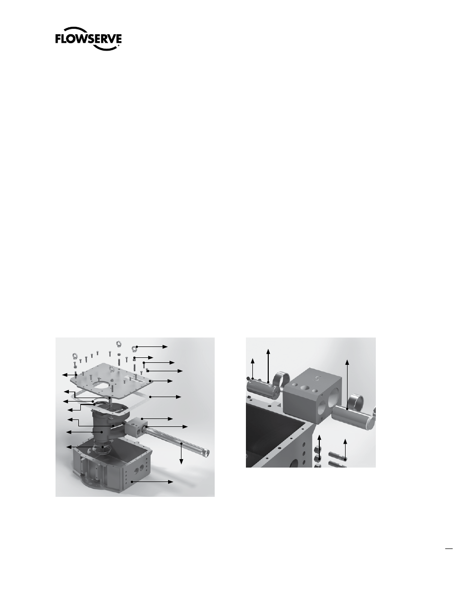
4.4 Scotch Yoke Housing Maintenance
Standard maintenance of the scotch yoke housing may take place in the field, without the need to disassemble the
spring container or the hydraulic cylinder. Perform the following steps. The reference drawing is Figure 21 and 22.
Figure 22: Exploded View of Housing
Figure 21: Exploded View of Adaptor Kit
53
54
55
57
56
38
39
40
41
42
43
44
45
46
47
48
49
50
51
35
36
37