Installation, Worcester controls – Flowserve 10 ACCESS I 39 Actuators with DeviceNet Interface User Manual
Page 2
2
10, 15, 20 ACCESS I 39 Actuators with DeviceNet Interface
WCAIM2019
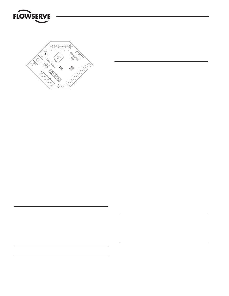
The solenoid connects to terminal block P4 terminals 3 and 4.
Positive 24 VDC is supplied to the solenoid coil from terminal 3 and
the solenoid coil return is connected to terminal 4. The solenoid is
energized by turning on a transistor which connects the return to
ground. Should it be necessary to operate a second 24 VDC 3 watt
device from terminals 1 and 2, terminal 2 is the positive supply and
terminal 1 is the return.
The circuit board has three 10 position rotary switches on board
(SW1, SW2, and SW3). SW1 and SW2 are used to set the MACID of
the board (i.e., address), with SW2 used for the most significant bit
and SW1 used for the least significant bit, e.g., for a MACID of 35,
SW2 would be set to 3 and SW1 would be set to 5. Valid MACID
values range from 00 to 63. A none-valid MACID setting on the
switches allows the MACID to be set through software.
SW3 is used to set the DeviceNet baud rate. Valid baud rate selections
are 125k, 250k, and 500k. SW3 position 0 represents 125k, SW3
position 1 represents 250k, and SW3 position 2 represents 500k. If
the SW3 position is set to an invalid setting it permits the baud rate to
be set through software.
NOTE: WHENEVER THE BAUD RATE AND/OR MACID IS CHANGED
VIA THE SWITCHES, THE BOARD POWER MUST BE CYCLED IN
ORDER FOR THE CHANGE TO TAKE EFFECT.
For additional information see Installation, Operation and Maintenance
Supplements 1, 2 and 3 that accompany this product.
a
WARNING: SERIES 39 ACTUATORS ARE ELECTROMECHANICAL
DEVICES SUBJECT TO NORMAL WEAR AND TEAR. ACTUATOR LIFE
IS DEPENDENT UPON APPLICATION AND ENVIRONMENTAL
CONDITIONS. IF APPLIED IN HAZARDOUS SERVICES, SUCH AS,
BUT NOT LIMITED TO, MEDIA TEMPERATURE EXTREMES, TOXINS,
FLAMMABLES, OR OTHER SERVICES WHERE IMPROPER OR
INCOMPLETE OPERATION COULD PRODUCE A SAFETY HAZARD, IT
IS INCUMBENT UPON THE SYSTEM DESIGNER AND THE USER TO
PROVIDE PROPER WARNING DEVICES SUCH AS TEMPERATURE
SENSORS, OXYGEN SENSORS AND FLOW SENSORS.
CAUTIONS: When actuator is installed in outdoor conditions, water
can enter the exhaust hole(s) of the control block and then freeze.
Flowserve suggests a cover be used, or mount the actuator such
that the block exhaust hole(s) will not fill with water.
Flowserve recommends that all products which must be stored
prior to installation be stored indoors, in an environment suitable
for human occupancy. Do not store product in areas where
exposure to relative humidity above 85%, acid or alkali fumes,
radiation above normal background, ultraviolet light, or
temperatures above 120°F or below 40°F may occur. Do not store
within 50 feet of any source of ozone.
IMPORTANT: INCLUDED IN ALL 39 ACTUATOR ACCESSORY AND
REPAIR KITS IS A REBUILD/ACCESSORY ADDITION LABEL, WHICH
IS TO BE MARKED WITH A PERMANENT MARKER AND THEN
APPLIED TO THE ACTUATOR AFTER AN ACCESSORY KIT HAS BEEN
INSTALLED OR AN ACTUATOR HAS BEEN REPAIRED
INSTALLATION
NOTE: The Series 39 actuator is normally installed with its major axis
parallel to the pipe line. This is mandatory when mounting actuator to
90° V1 diverter/three-way (D44 and T44) valves and CPT valves. The
actuator can be oriented above, beside or beneath the valve without
affecting its operation.
Rev. R6 actuators may come with an ISO locating ring used for
optional ISO mounting.
A. Determine mode of operation desired (normally open or normally
closed) of the valve.
B. Determine desired quadrant for bracket attachment and direction
of mounting of actuator (inline or cross-line).
C. Attach mounting bracket to actuator using four (4) cap screws
and lockwashers provided in mounting kit. To avoid any damage
to the Series 39 actuator body, ONLY the proper length screws
supplied with the mounting kit should be used. For
1
/
4
"–2" top
mount style valves, attach bracket such that bracket nameplate
will be to side of valve.
For mounting to 818/828 Series valves, insert ISO locating ring
into groove on bottom of actuator before attaching to bracket.
NOTE: Ring can be permanently held in groove by applying Loctite to
ring before inserting in groove.
D. Attach bracket/actuator assembly to valve as follows:
CAUTION: Ball valves can trap pressurized media in the cavity.
If it is necessary to remove any valve body bolts, stem nuts or
remove valve from the line, and if the valve is or has been in
operation, make sure there is NO pressure to or in the valve
and operate valve one full cycle. However, the valves
mentioned here do not require the removal of any valve body
bolts or removal of valve from line in order to mount actuator.
1. Rotate valve ball and stem to position necessary to achieve
desired operation. If any valve information is marked on stop
plate or handle, it will be necessary to transfer this
information to the bracket nameplate.
2. For
1
/
4
"-2" 44,
1
/
2
"–2" WK70/WK74,
1
/
4
"–1
1
/
2
" 59, and
1
/
2
"–1
1
/
2
" H71
Series top mount style valves and
1
/
2
"–2" 51/52,
1
/
2
"–1
1
/
2
" 82/83
Series valves with high-cycle stem packing as standard,
Flow Control Division
Worcester Controls
DeviceNet Board Layout