Worcester controls – Flowserve 10 ACCESS I 39 Actuators with DeviceNet Interface User Manual
Page 7
WCAIM2019
10, 15, 20 ACCESS I 39 Actuators with DeviceNet Interface
7
Flow Control Division
Worcester Controls
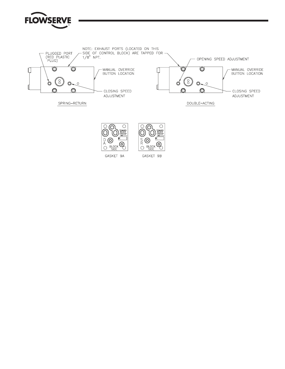
Figure 1
spring complement is installed). When checking supply
pressure, place gage inline at control block inlet and monitor
gage for unexpected pressure drops.
B. If proper voltage and air pressure have been verified and valve is
free, proceed as follows:
1. Turn on signal voltage. Check solenoid for clicking sound.
2. If no sound is detected, remove air pressure and turn off
signal voltage.
a. Carefully unscrew solenoid and solenoid stem from end
cap.
b. Reapply signal voltage and observe solenoid plunger. If it
does not retract, replace solenoid.
3. Manually override control block. If correct operation is not
obtained, replace the control block.
4. If control block and solenoid are operating correctly, proceed
to next section.
C. If the actuator functions but exhibits leakage or power loss
accompanied by leakage, proceed as follows:
1. Check voltage. Voltage must be within 10% of the specified
voltage (low voltage will cause leakage out of the back of the
solenoid and burn out of the coil).
2. Check air supply. Be certain that no sharp air pressure drops
occur as unit is cycled. Loss of air pressure can cause
incomplete shifting of the spool valves, which results in
bypass leakage and substantial actuator torque losses.
3. If air supply and voltage are adequate, proceed as follows:
a. If leak is at solenoid exhaust port, replace the solenoid.
b. If leak occurs at exhaust ports in the block itself, the
trouble will be in either the spool valve in the block, or at
one of the piston seals of the actuator. A leaking piston
seal will usually leak on either cycle.
If the block is replaced and leakage continues from the
exhaust port, remove the actuator from the valve,
disassemble (per Rebuilding Instructions on page 8) and
check the following:
1) Make sure that all internal porting is free and clear of
any obstructions. End caps, guide rods and the piston
with hole are air transporting components.
NOTE: The most common problem encountered on
39 actuators is the improper replacement of the
piston with hole relative to seals in end caps. (See
Step 5 on page 9.)
2) Make certain that the actuator has lubrication, and
that there is no solidified grease between the pinion
and the piston racks.
a) If actuator has no lubrication, apply generous
amount of a #1 grease.
b) If solidified grease between the pinion and the
piston racks is present, clean, dry, regrease and
reassemble.
Figure 2