Worcester controls – Flowserve 10 ACCESS I 39 Actuators with DeviceNet Interface User Manual
Page 9
WCAIM2019
10, 15, 20 ACCESS I 39 Actuators with DeviceNet Interface
9
Flow Control Division
Worcester Controls
3. Replace the two split-ring style bearings (6A) and one guide rod
O-ring (15B) in each end cap.
Replace the split-ring style bearing (6B) and guide rod O-ring
(15B) into I.D. grooves in each piston. Install O-rings (15C) onto
pistons.
4. Replace O-ring (15E) and bearing (15H) on the bottom of shaft.
On the top of the shaft add the two stainless steel washers with
the thrust bearing (10) between them. Locate the top bearing
(15G) and O-ring (15D) into the body. NOTE: Top bearing (15G) is
flat, the same as and interchangeable with thrust bearing (10).
Replace the shaft through the larger opening in the bottom of the
body.
5. Very carefully align the piston guide rod assemblies inside the
body. Keep the pistons square to the body.
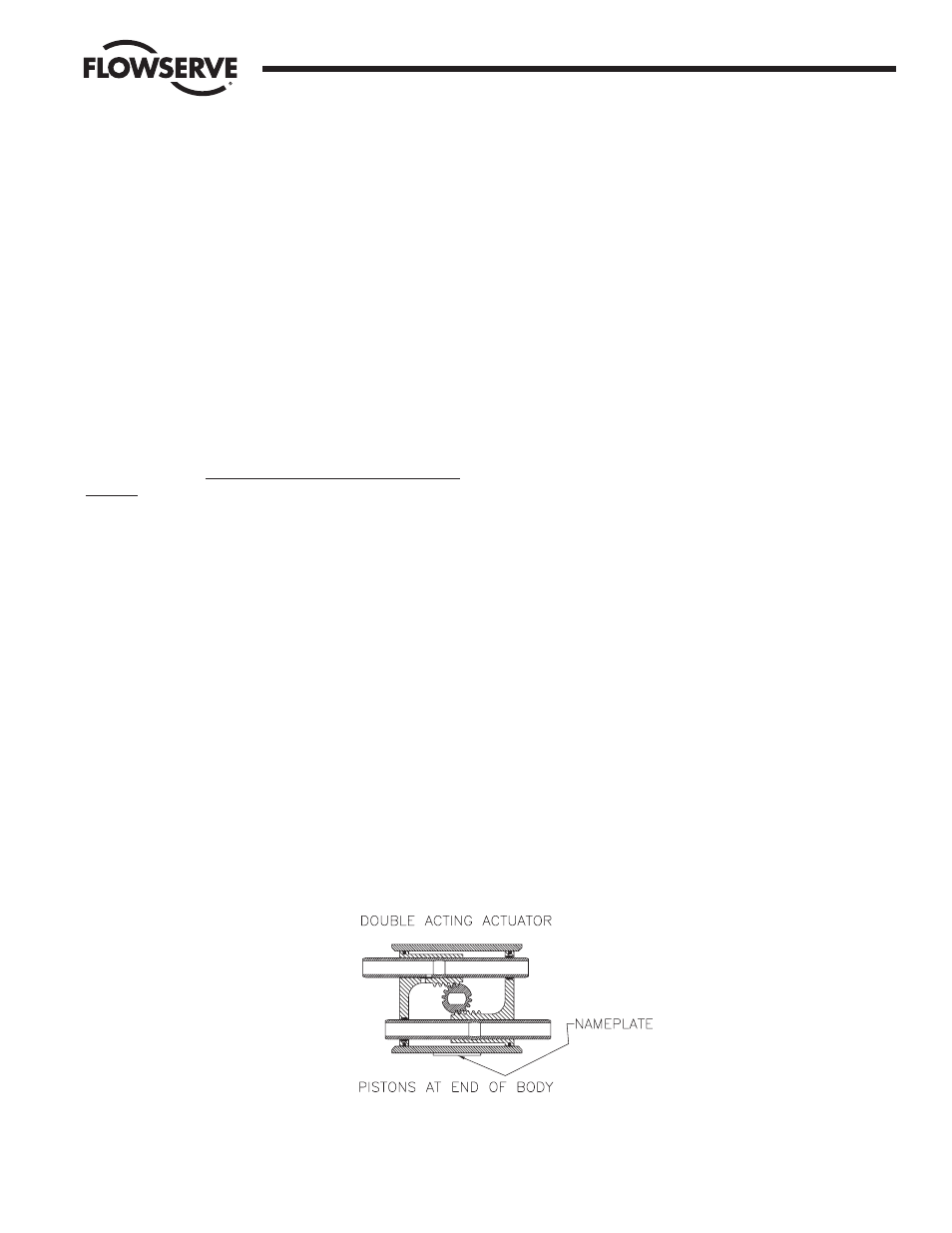
IMPORTANT: One piston guide rod assembly has a through-hole
drilled in it. It can be easily located by looking down the ends of both
guide rods. This piston assembly must be reassembled, with its
respective guide rod, opposite the nameplate on the body, as it was
removed.
6. Align the shaft so that the teeth on the shaft will “pick-up” the
piston assembly’s rack teeth when turning the top extension of
the shaft clockwise (CW). (See Figure 3 below.)
IMPORTANT: Proper 90° rotation can only be ensured if the shaft
teeth begin to mesh with the piston assembly’s teeth at the “proper
tooth” between these meshing gear pairs. (See Figure 3 below.)
7. To ensure proper meshing of teeth, move the shaft 15 to 20
degrees counterclockwise (CCW) from its normal position when
the piston assemblies are located at the body ends. NOTE: The
“normal position” of the shaft is when the top flats are parallel to
the main axis of the actuator body.
8. With the piston assemblies in the body, gently push each piston
into the body. Turn the top shaft extension clockwise (CW). Do
not allow the pistons to “cock”.
At the proper point of engagement between the shaft and piston
assemblies, both piston assemblies will move toward the center
of the body when turning the top shaft extension of the actuator
clockwise (CW).
9. Once the shaft and pistons are properly engaged, ensure that
smooth movement and full-closed operation can occur without
moving the pistons out of the actuator body. This is important!
10. Install O-ring (15A) into and replace the actuator end caps, (5A
and 5B), noting that the “foolproof” pin between the body and end
cap mates properly. For spring return actuators, see spring
installation section on page 10 before installing end caps.
NOTE: When installing the end cap O-rings, use a small amount of a
general purpose lubricant, such as petroleum jelly, to hold them in
place for ease of assembly and to avoid having them fall and get
pinched.
11. Replace the stainless steel washer over the top shaft extension.
12. VERY IMPORTANT:
Install the NEW shaft clip (15F) into its mating groove on the top
shaft extension. The removed shaft clip is not to be reused.
Place the numbered side up on the shaft clip and be certain the
clip is fully seated in its groove. See Note in paragraph 7 of
Actuator Disassembly on page 8 for installation of spiral-ring type
shaft clip (which newer repair kits will contain).
13. If control block (7A) was removed:
Properly insert appropriate gasket (9A or 9B) between control
block or air connection block and end cap (see Figure 2 on page 7
and actuator exploded view), and attach block securely to end
cap. Do not apply any grease to gasket, it must be installed dry.
14. Replace position indicator (17) (if any). See Section D.8. in
Installation Section for proper installation and to determine
position indication.
15. Mark Rebuild/Accessory Addition Label, if included in repair kit,
and apply to actuator.
Figure 3
IMPORTANT: Note the relative location of the shaft teeth and the
piston assembly’s rack teeth. The above figure is viewed when
looking at the top of the actuator.