Rebuilding instructions, Actuator disassembly, Actuator reassembly – Flowserve 10 ACCESS I 39 Actuators with DeviceNet Interface User Manual
Page 8: Worcester controls
8
10, 15, 20 ACCESS I 39 Actuators with DeviceNet Interface
WCAIM2019
Flow Control Division
Worcester Controls
3) Verify that actuator pinion shaft and/or pistons are
not bound. If bound, reassemble per Rebuilding
Instructions.
4) If unit exhibits excessive amounts of backlash, check
teeth on piston racks for wear. If worn, replace piston
assemblies.
5) In spring return actuators, check for misplaced or
broken springs. If springs are broken, check body
bore for scoring.
a) If springs are broken, replace springs. SPRINGS
SHOULD ALWAYS BE REPLACED IN COMPLETE
SETS.
b) If body bore is scored, replace it. Also, replace
piston O-rings (contained in repair kit).
6) If actuator is free, valve is free and control block, if
used, is shifting air properly, reassemble the actuator
and retest. If unit still fails to operate, consult
Flowserve.
REBUILDING INSTRUCTIONS
NOTE: For identification of all numbered parts discussed below,
consult exploded view of actuator.
After actuator has been repaired, mark rebuild label accordingly and
apply to actuator.
ACTUATOR DISASSEMBLY
1. Disconnect the air supply and electrical service to the actuator.
2. Remove the actuator and its mounting bracket from the valve.
(See Caution note below.)
CAUTION: Ball valves can trap pressurized media in the cavity.
Isolate the piping system in which the actuator valve assembly
is mounted and relieve any pressure on the valve. For all
valves listed in Installation Section D, the actuator bracket can
be removed without loosening or removing any valve body
bolts.
3. Remove the actuator bracket from the actuator to begin repair.
(Note mounting of removed bracket for easy reassembly.)
4. It is not necessary to remove the control block (7A) to rebuild
actuator. However, if it becomes necessary to remove the block,
begin by removing the block bolts (7D). Use care to retain the
block gasket (9A or 9B).
5. Each end cap (5A and 5B) is aligned onto the body (1) over a
“foolproof pin.” This ensures that the end caps can only be
assembled to their respective end of the actuator. Remove all four
metric screws (5C) from and remove both end caps. Remove the
two bearings (6A) and O-rings (15A and 15B) from each end cap.
CAUTION: If the actuator is a spring-return model, first remove
two end cap screws diagonally opposite each other, then
lubricate the threads and under the head. Replace the screws
and repeat procedure for the other two screws. Do this for each
end cap as this will aid reassembly. Now uniformly loosen all
four end cap screws on each end cap two to three turns at a
time, in sequence, to relieve pre-load of the springs. On larger
actuators with springs use caution when removing end caps.
End cap screws are long enough to allow springs to relieve
before disengaging.
After the screws are removed, gently pry off each end cap, being
careful not to damage the end cap O-rings.
6. The two piston guide rod (4) assemblies can now be removed from
each end of the body and disassembled by removing the piston set
screws (12). Do not interchange piston guide rods (4) and their
respective piston (3). For some actuators, each guide rod and
piston may be press fitted together (do not use set screws) and
cannot be disassembled. (To assist reassembly, mark the body with
a line on the side from which the guide rod using the through-hole
is removed). Remove all O-rings (15B) and (15C) and bearings
(6B) from pistons (3).
7. The shaft (2) can only be removed after piston assemblies are
taken out. Remove the position indicator (17) (if any), the shaft
clip (15F) (not a reusable part!) (see Note below) and the
stainless steel washer from the top of shaft. Then remove the
shaft through the larger opening in the bottom of the body. The
top bearing (15G) and the O-ring (15D) can now be removed.
Remove the two stainless steel washers and thrust bearing (10)
from the top of the shaft and the O-ring (15E) and bearing (15H)
from the bottom end.
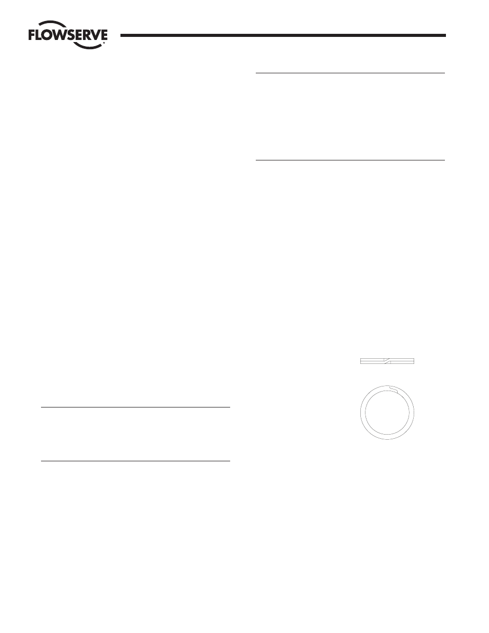
NOTE: Some actuators may
be using a spiral ring type
shaft clip as shown at right.
To remove this clip,
engage the lower end of
the ring with a flat blade
screwdriver. Using
another flat blade
screwdriver push the top
end of the clip in the opposite direction. As the clip I.D. expands,
lift the clip from the shaft. The installation of a new clip would be
the above steps in reverse and ensuring that the edges of the clip
are properly seated in the shaft groove.
ACTUATOR REASSEMBLY
1. Be sure the actuator surfaces are clean and free of grit and
scratches. If the inside walls of the body are scored, or the guide
rod surfaces are scratched, the actuator will leak after rebuilding.
New parts should be obtained from the factory. Light tracking,
barely detectable to touch, is acceptable.
2. All rebuilding kit O-rings and bearings may now be installed.
Lubricate the standard actuator thoroughly with a #1 grease.
Apply a light film of grease to all O-rings. (Note that kits also
contain some parts for earlier revisions of actuators which will
not be needed.)