3 electrical installation and adjustment – Flowserve 75 Series DeviceNet Interface User Manual
Page 3
FCD WCAIM2068-00
DeviceNet Interface for Series 75 Electric Valve Actuator
3
1
⁄
6
turn. Excessive tightening causes higher torque and shorter
seal life.
NOTE: For both large valves with V51 high cycle stem packing
option installed (identified by two Belleville washers installed and
handle assembly, stop and stop screws removed), and 818/828
Series valves, no stem area disassembly is required.
For ½"–2" 94 valves, remove handle (if any). For 3"–6" 94 and
2"–8" E818/828 valves, remove handle assembly, stop and
spacer (if any). Do not remove gland plate or gland bolts.
For 2"–8" 818/828 valves, remove handle assembly, locking
plates and hardware, and stop screw (if any). Do not remove
stop plate (2"–6" Sizes) or spacer (8" Size).
c. Center coupling on valve stem.
d. Lower mounting bracket/actuator assembly over coupling and
onto valve, making sure that male actuator shaft engages slot in
coupling.
e. Secure bracket to valve using cap screws and Iockwashers, or
bolts and nuts provided in mounting kit. Tighten securely. For
small size top mount style valves, bracket nameplate is on the
side of valve.
f. Install set screws (if any) in the coupling and tighten securely.
3 Electrical Installation
and Adjustment
A. To gain access to terminal strip, it is necessary to remove the
actuator cover.
General Purpose: Loosen cover screws and lift cover from unit.
W, X and Z: Remove declutch knob screw and lift knob from
shaft. Remove the two cover screws from cover (the other six
screws are in an envelope and inside the cover) and lift cover
from unit.
B. Make conduit connection to NPT fitting on actuator base.
Connect power supply to actuator terminal strip, as shown on
electrical schematic diagram(s) located inside actuator cover
and also in this manual.
The actuator should be electrically grounded in accordance with
standard procedures.
For W, X and Z actuators, connect a CSA-certified 18 AWG
green-colored grounding wire to the green-colored grounding
screw on actuator base.
See Table 1 for minimum fuse rating when overcurrent protec-
tion is used in motor power circuit.
a
CAUTION: In cases where the conduit connected to the
actuator may be partially or completely run underground, or
through which moisture may contact energized live parts, or
where the actuator and/or conduit is exposed to tempera-
ture differences, the power and DeviceNet conduits should
be sealed within 18" of the actuator in accordance with the
National Electrical Code.
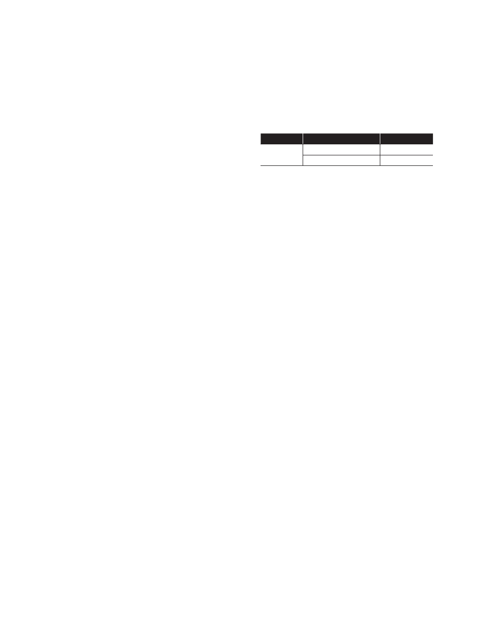
Table 1
Actuator Size
Voltage
Fuse Rating
10–23
120 VAC
5 A
240 VAC
3 A
NOTE: The table shows the minimum rating to prevent inrush
current from blowing the fuse.
C. Connections to the 75 Actuator/DeviceNet Circuit Board
The customer's field connections to the circuit board take place
on terminal block P3 as follows:
Terminal 1: Bus negative from 24 VDC supply (next to the
P3 label)
Terminal 2: CanL signal
Terminal 3: Bus Shield
Terminal 4: CanH signal
Terminal 5: Bus positive from 24 VDC supply
The switch/sensor connections are made to the terminal block
labeled as P2. Terminal 1 is located next to the P2 label.
The switches/sensors are wired to the terminals such that termi-
nals 1 and 2 are for SW3 CW direction and terminals 3 and 4 are
for SW4 CCW direction.
The CCW slave relay connects to terminal block P4 terminals 3
and 4. Positive 24 VDC is supplied to the relay coil from terminal
3, and the relay coil return is connected to terminal 4. The relay
is energized by turning on a transistor, which connects the
return to ground. When the relay is energized, the normally open
contact closes and then switches the hot side of the power sup-
ply to the motor(s) to rotate the actuator in the CCW direction.
The CW slave relay connects to terminal block P4 terminals 1
and 2. Positive 24 VDC is supplied to the relay coil from terminal
2, and the relay coil return is connected to terminal 1. The relay
is energized by turning on a transistor, which connects the
return to ground. When the relay is energized, the normally open
contact closes and then switches the hot side of the power sup-
ply to the motor(s) to rotate the actuator in the CW direction.
The circuit board has three 10-position rotary switches on
board (SW1, SW2 and SW3). SW1 and SW2 are used to set the
MACID of the board (i.e., address), with SW2 used for the most
significant bit and SW1 used for the least significant bit (e.g., in