4 options (factory-installed) – Flowserve 75 Series DeviceNet Interface User Manual
Page 4
4
DeviceNet Interface for Series 75 Electric Valve Actuator
FCD WCAIM2068-00
a MACID of 25, SW2 would be set to 2 and SW1 would be set to
5). Valid MACID values range from 00 to 63. A nonvalid MACID
setting on the switches allows the MACID to be set through
software.
SW3 is used to set the DeviceNet baud rate. Valid baud rate
selections are 125k, 250k and 500k. SW3 position 0 represents
125k, SW3 position 1 represents 250k and SW3 position 2
represents 500k. If the SW3 position is set to an invalid setting,
it permits the baud rate to be set through software.
NOTE: Whenever the baud rate and/or MACID is changed via the
switches, the DeviceNet board power must be cycled in order for
the change to take effect.
D. Switch Cam Settings:
Switch configuration is as follows (when viewed from the termi-
nal strip side of the actuator):
Actuator shown at 0° position (all the way CW).
Cam settings are as follows:
Switch 1: Trips at 0°. Full CW.
Switch 2: Trips at 90°. Full CCW.
Switch 3: Trips at 2°.
Switch 4: Trips at 88°.
Figure 1
����������
���
���
���
���
������
�
���
�
���
�
�
�������������
�����������
���
���
����������
������
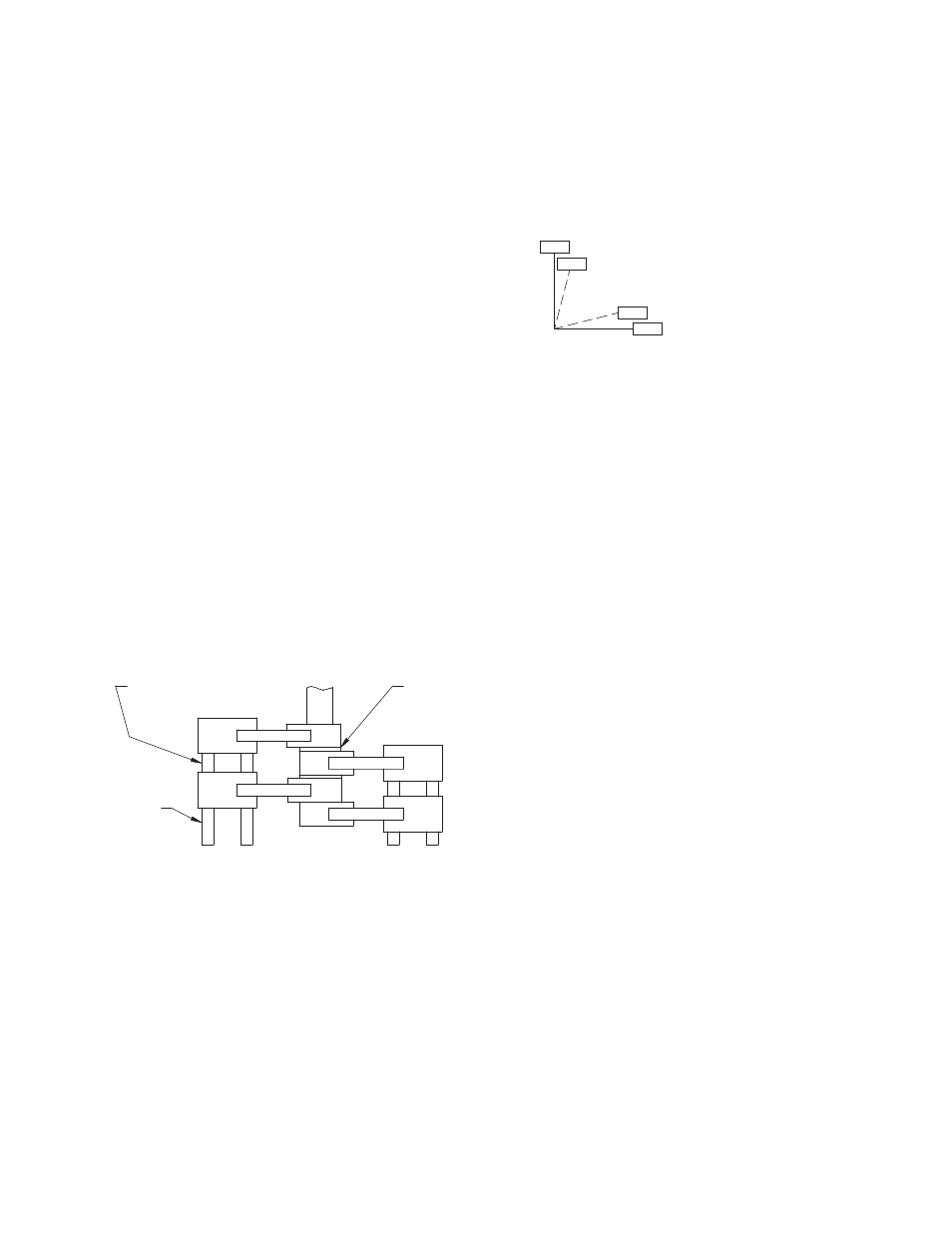
The positioner employs a total of four cams, two for the end
of stroke limit switches and two for the position indication
switches.
Figure 2 shows actuator shaft location as viewed looking down
on the shaft.
1. Adjust the CW limit switch 1 cam so that the valve shaft has
a position of 0° when movement stops.
2. Adjust the CCW limit switch 2 cam so that the valve shaft
has a position of 90° when movement stops.
3. Adjust the CW position indication switch 3 cam 2° to 3°
before the CW end of travel (i.e., +2° to +3°). If the cam is
properly adjusted, the CW LED (SW3) will be closed when
the valve is in the full CW position.
4. Adjust the CCW position indication switch 4 cam 2° to 3°
before the CCW end of travel (i.e., +87° to +88°). If the cam
is properly adjusted, the CCW LED (SW4) will be closed
when the valve is in the full CCW position.
Figure 2
���
���
���
���
��������������
������������
��������������������
��������������
��������������������
����������������������������
E. Replacing Actuator Cover
NOTE: For W and Z models, make sure flange gasket/seal is
properly installed. Tighten all cap screws securely.
For X and Z models only:
After placing the cover on the actuator, tighten the cover bolts in
a crisscross fashion to a torque of 70–80 in-Ib.
A feeler gage,
1
⁄
8
" to ½" wide and .0015" thick, shall be used to
check the clearance between the base and cover flange. This
feeler gage shall not penetrate the base/cover flange gap any
more than
1
⁄
8
".
Replace declutching knob, taking care that knob set screw
engages milled flat on clutch shaft and indicates proper position
on labeled cover.
4 Options (Factory-Installed)
A. Mechanical Brake
NOTE: Mechanical brake should require no adjusting.
1. Testing and Troubleshooting:
a. Energize actuator for rotation in both open and closed
directions. At the rated actuator voltage, the brake coil is
energized and moves the plunger to release brake arm.
Clearance of .020" to .030" must exist between the brake
arm and the brake disc when power is applied to the
actuator.
b. If the brake arm is too close to the brake disc, realign
the coil housing so that coil plunger can move farther
toward the center of the actuator, permitting more
movement of the brake arm.
c. Plunger chattering indicates a low supply voltage. If
actuator voltage is at the rated conditions, realign coil
housing so that coil moves away from the center of the
actuator to reduce plunger movement.