2 star measurement technique – Fluke Biomedical 07-611 User Manual
Page 15
Operation
X-Ray Tube Focal Spot Measurements
2
2-9
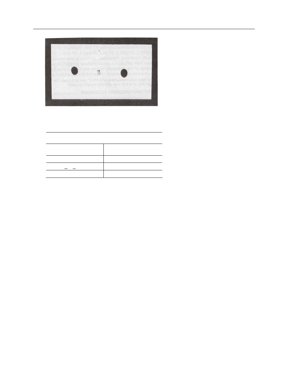
Figure 2-10. Pinhole Image with Localization Holes
Table 2-3.
Suggested Focal Spot Size Tolerances
(For Pinhole Camera Method)
Nominal Focal
Spot Size (F, mm)
Tolerance (%)
Minus
Plus
F < 0.8
0
50
0.8
< F < 1.5
0
40
F > 1.5
0
30
2.2 Star Measurement Technique
2.2.1 Physical Description of Star Test Pattern
The Model 07-503, 07-503-1 and 07-503-2 consists of 60 spoke pairs divided into four 15° sectors. Each
spoke diverges at an angle of 0.5°.
The Model 07-509, 07-509-1 and 07-509-2 consists of 44 spoke pairs divided into four 45° sectors and
diverging at an angle of 2° for each spoke.
The Model 07-510, 07-510-1 and 07-510-2 is divided into 90 spoke pairs; each spoke diverges at an
angle of 2°.
The Model 07-542, 07-542-1 and 07-542-2 consists of 56 spoke pairs divided into four 28° sectors and
diverging at an angle of 1° per spoke.
The Model 07-543, 07-543-1 and 07-543-2 consists of 48 spoke pairs divided into four 35° sectors. Each
spoke diverges at an angle of 1.5°.
2.2.2 Instructions
for Use
Focal spot size can be determined with the 07-503, 07-503-1, 07-503-2, 07-509, 07-509-1, 07 -509-2, 07-
510, 07-510-1, 07-510-2, 07-542, 07-542-1, 07-542-2, 07-543, 07-543-1 and 07-543-2 test patterns by
observing the regions of blurring which occur when the star pattern is radiographed. Radiation from
different areas of the focal spot will cause a periodic blurring of the pattern image. Knowledge of the
geometric factors and the distance from the center of the pattern to the region where blurring occurs will
permit the calculation of the focal spot size.