Over-table x-ray – Fluke Biomedical 07-611 User Manual
Page 8
Nuclear Associates Radiographic and Mammographic Focal Spot Measurement Products
Operators Manual
2-2
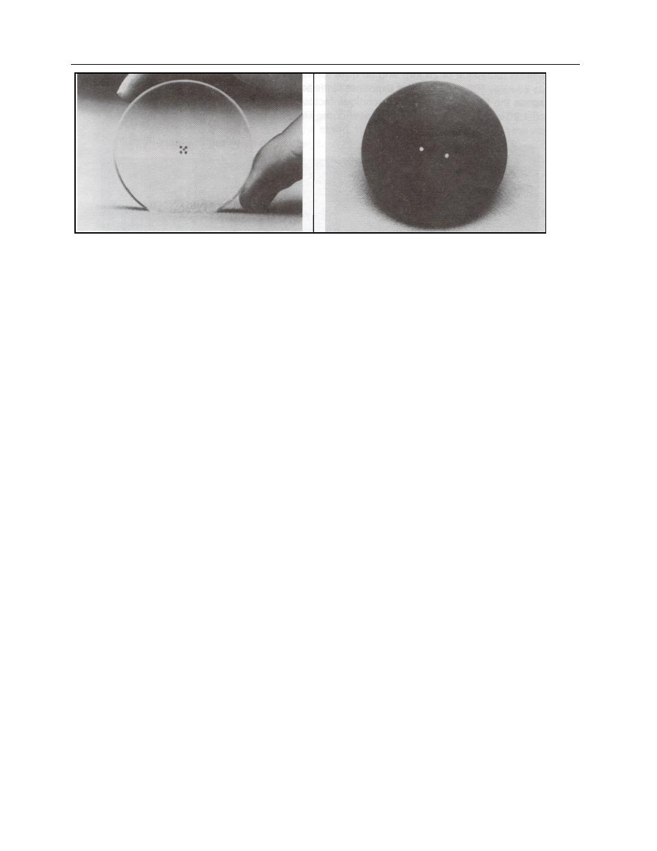
Figure 2-2. Focal Spot Test Stand Alignment Device Figure 2-3. Magnification Insert
2.1.3 Equipment Needed/Recommended for Mammographic X-Ray Tube Focal
Spot Measurements
1. Slit assembly, Pinhole, or Star Pattern.
2. A Focal Spot Test Stand (See Figure 1-1), with adapter ring, fluorescent screen and Magnification
insert (Figure 2-3).
3. Focal Spot Test Stand Alignment Device (Figure 2-2).
4. 18 x 24 cm mammography cassette and film and 8" x 10" direct exposure x-ray film.
5. Clear plastic metric ruler.
6. Spirit
level.
7. 6X magnifier with graticule scale in 0.1 mm divisions.
2.1.4 Procedure for
Over-Table X-Ray
Tube Focal Spot Test Stand Alignment
1. Remove all objects between the focal spot and table, e.g., compression device, diaphragms, cones,
etc., which can be removed easily.
2. Place the focal spot test stand on the imaging table* (Figure 2-4).
3. Place the test stand alignment device in the top of the focal spot test stand (Figure 2-5).
4. Align the array of four beads so they are parallel with the anode-cathode axis of the x-ray tube.
5. Adjust the alignment device-to-film distance and focal spot-to-film distance (if variable) to obtain the
correct magnification factors (Table 2-1).
6. Level the base of the test stand with the spirit level, using the unit adjustments. Verify that the top of
the test stand is also level.
7. Place the fluorescent alignment screen on the test stand base plate.
8. Set a radiographic technique of about 28 kVp, 50 mA, and 2 sec for mammographic units. For R/F
units set the radiographic technique at 75 kVp, 50 mA and 2 sec.
9. Rough alignment* can be carried out using the collimator light with the room lights off.
10. Turn off all room lights and view, on the fluorescent screen, the x-ray image of the five beads*.
(This usually requires two people.)
11. Shift the test stand to assure that the stand is aligned with the central ray*, i.e., the one bead is
centered between the four beads (Figure 2-6).
12. Replace the test stand alignment device with the magnification insert.
13. Place the direct exposure x-ray film in the test stand tunnel.
* Unlike conventional x-ray equipment, the central or perpendicular ray is usually located near the edge of the x-ray field,
i.e., near the chestwall side.