2 instrument features, Figure 2-1. input circuit schematic – Fluke Biomedical 35035 User Manual
Page 8
35035
Operators Manual
2-2
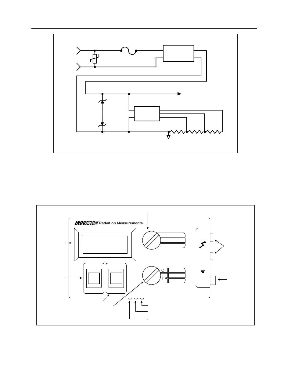
Figure 2-1. Input Circuit Schematic
2.2 Instrument Features
Figure 2-2 represents a front panel of the Model 35035 mA/mAs Meter and shows the location of its
display, input jacks, fuse, switches, and trimmer adjustment controls. The functions of these features are
described below.
Figure 2-2. Model 35035 mA/mAs Meter Front Panel
FA2526-
1.003
FA2526-
9.026
FA2526-
90.262
R1
R2
R3
FUNCTION
AND MODE
SWITCHING
IN
5359A
IN
5359A
V130
LA
10A
R15
HI
LO
INPUT
AC/DC MODE
SWITCHING AND
RECTIFIER
TO METER ELECTRONICS
F1
2A
D2
D3
mA/mAs METER Model 35035
INPUT
JACKS
FUSE
ASSEMBLY
MODE SWITCH
FUNCTION SWITCH
RESET
SWITCH
DISPLAY
RANGE SWITCH
OFF
mA
mAs
2000
200
20 ( mA)
RESET
DC
AC
HI
LO
500V
MAX
250V
WARNING! High voltage may be present during use.
DISPLAY ZERO ADJUST
mA GAIN ADJUST
mAs GAIN ADJUSTMENT
F 2A H